| ||||||||||||||||||||||||||||||||||||||
| ||||||||||||||||||||||||||||||||||||||
Jaguar XJInboard Rear Brake Upgrade(Replacing Solid Rotors w/ Vented Rotors)Small PartsCaliper Spacers: First and foremost, a set of
spacers are needed to widen the calipers. The calipers need
to be widened by the same amount that the rotor is wider than
OEM. We are talking about replacing the 1/2" solid rotor
with a 3/4" vented rotor so we need to use 1/4" spacers to widen
the calipers. Note that, if you happen to be upgrading a Series 1 E-Type, the
first thing you will have to do is upgrade to a later caliper
design. The Series 1-1/2, 2, and 3 E-Type and XJ6/12/-S
inboard rear brake calipers are all reportedly similar and will
fit the Series 1 E-Type with only minor fiddling.
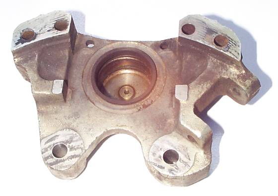
This is a picture of one half of a caliper -- the inboard half of the left side caliper, to be precise. The mating surfaces on either side at the top of the picture is where the spacers go. To make things really pretty, you need to cut out your spacers to the same shape as those mating surfaces so it looks really smooth when it goes together. However, for practical purposes, the cutout doesn't really need to be so precise. You should, however, make sure the spacer is at least as large as the mating surface of the caliper to give the mating joint a solid "footprint". Since those mating surfaces are less than an inch wide, you can use rectangular bar stock that is one inch wide and the desired thickness to make your spacers from. 1" x 1/4" rectangular bar stock is readily available. You can also make the spacers from 1/8" or even 1/16" stock; just make more of them and stack them up. Drill the two bolt holes first, then use the bolts to hold the
spacer against the caliper while you mark out the outline.
If it's of any help to you, you can set one half of a caliper on a
flatbed scanner, prop it up so the mating surface is sitting flat
against the glass, and scan yourself an actual-size image of the
mating face. You could, for example, print it on a sheet of
paper, tape it down to your piece of steel, and use a center punch
to mark the locations of the holes. On the edge facing the rotor, you need to make sure the edge of the spacer doesn't interfere with the rotor itself. The end of each spacer pointing towards the pad retaining pins can be left quite long, just make sure it doesn't interfere with the installation of the pins -- but they are more than 1/4" away. The spacer cannot possibly interfere with the pads themselves, since the spacer is 1/2" narrower than the rotor. The outer end on the end with the handbrake calipers must be short enough to avoid interfering with the bronze fork installation; the outer end on the other end (lower end in the car) can be almost any length. The spacer edge that is critical, believe it or not, is the upper edge in this picture, the one facing away from the rotor, the one facing forward in the car -- especially the spacer on the lower end of the caliper as it sits in the car, the one on the non-handbrake end of the caliper. Especially the one on the right side caliper. This surface just barely clears when removing or installing the caliper in the subframe. Make sure to grind it down to flush with the outer surface of the caliper itself in this area. Palm happened to have some 1/4" steel plate laying around (doesn't everybody?) so there was no need to purchase any bar stock. The stuff was good 'n rusty, so a little steel wool was in order. The completed spacers looked like this:
These spacers don't cost any money to speak of, but they do take some time to drill and cut out. Caliper Bolts: The next items needed are the 3/8"-24 bolts to hold the calipers together. Don't use the originals, they're too short and you want to make sure to engage enough threads to hold the halves together securely. The original bolts are 2-1/8" long -- but they're actually a bit too short to begin with! They could have been a quarter of an inch longer originally before you even start talking about spacing the caliper. For 1/4" spacers, 2-1/2" length would be good. Go with Grade 8 or "alloy steel" bolts; this is not a place for
scrimping on cheap bolts. It doesn't really matter what type
heads you find; socket head allen bolts might look cool! The
original bolts have no locking plates or lockwire because they are
fairly long bolts; the length will provide enough "stretch" when
torqued to ensure they won't vibrate loose. You can drill
holes in the heads for lockwire if you're that kinda guy. Be
sure to apply anti-seize compound to the bolt threads when
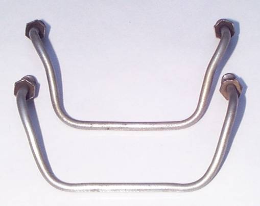
assembling. Bridge Pipes: You're going to need to do something about the bridge pipes, the pipes that connects the two halves of each caliper. They obviously are configured for a particular spacing between the fittings, and you've just increased that spacing by the thickness of the spacer. Since the spacers are only 1/4", you can actually bend the original tubes just a bit and make them fit.
In this picture, the upper bridge pipe is the original shape. The lower one has been suitably bent to fit a caliper with 1/4" spacers in it. Note that the bending needs to not only address the additional distance between the ports, but it also must result in a configuration that will clear the corners of the caliper and the handbrake pivot pins. It is advisable to have a caliper assembled, with spacers, on hand when doing this bending. If you prefer, you can have some new bridge pipes made. This isn't difficult; pre-made brake lines are available in auto parts stores, totally straight -- you have to bend them to the shape you need. Make very sure you get the correct type fittings; they need to have the correct threads (3/8"-24) and they need to have the correct style of tip.Brake Pad Retention Pins: The pins that hold the main caliper pads in place have to be replaced because the originals are now too short by the thickness of the spacer. This is a really easy job; in fact, there are four ideas presented here. The first is the way Palm went, which was to make new pins from really long 1/4" bolts. The original pins are 2-5/8" long under the head, so the 1/4" bolts need to have a smooth shank at least that long plus the 1/4" thickness of the spacer. Palm bought 4" long 1/4" hex head Grade Nil (there's no need for strength here) bolts at Wal-Mart, where they come two to a pack (with nuts!) for less than a buck. Saw the threaded end off, then chuck the rest of the bolt up in a lathe or drill and grind the head down to something that looks nice. Note that of the four holes these pins must fit through in each caliper, one is recessed, so the head must be ground down at least far enough to fit into that recessed hole. Finally, drill a 1/16" hole for the clip the same distance from the headed end as on the original, and you're done. Can be done in just a few minutes.
In this picture, the upper pin is the original. The middle one is the longer one made from a bolt; at the bottom is the type bolt it was made from. Another idea is to purchase a length of 1/4" steel rod (available at hardware stores), cut it into suitable lengths, and drill two holes in each for clips to hold them in place. You need the second hole to make up for the lack of a head. Drill the two holes located so that the clips will be just inside the openings in the calipers, with enough space to allow it to rattle a little. The prime disadvantage of this method is that you're going to have to find four more clips! The advantage, though, is that once the clips are removed, the pins can come out either direction. Yet another solution is to buy some genuine Girling brake pad retention pins that happen to be longer. They're not too hard to find, either -- they're about 8 feet away at the other end of the same car! Yes, the pins used at the front end of the XJ will fit perfectly; they are part number 12798. After Palm thought about things a little more, he decided that installing the clips in the vicinity of the caliper dust boots -- where they were originally -- may not be wise, even though the problem of these clips damaging the boots appears to be more of a concern on the front brakes. It is easy enough to drill new 1/16" holes out at the end of the pins and put the retaining clips outside the calipers.
If you concur with this notion, the idea of using steel rod and
two clips goes away because one end of one pin in each caliper
fits into a recessed hole, and the clip won't fit. It does
bring us to a fourth possibility, though, and that is to purchase
generic "clevis pins" in 1/4" x 3.00" size. The hole for the
clip is already in the correct spot to be outside the caliper, no
drilling required! They're cheap, too, apparently; here's a
pack
of 25. Here's a pack
of 5 in 18-8 stainless steel. Handbrake Caliper Links: A concern with using the handbrake calipers with a thicker disc is the link that connects the two handbrake caliper halves. This is part of the adjuster; one end is threaded so the adjuster can operate by turning a threaded cogwheel on it, and the other end is pinned so it cannot rotate. It looks kinda like a long screw with a slotted head. When the calipers get 1/4" farther apart, these links needs to be 1/4" longer -- or do they? The adjustment range on the existing links does seem to be long enough to deal with 1/4" spacers -- but just barely. To properly assemble the handbrake system, the adjusters need to be adjusted quite a bit loose and the bronze fork tines configured to hold the pads away from the rotor. When assembled, the handbrake levers should be manipulated back and forth repeatedly until the adjusters pull the pads against the rotor and preload the bronze fork tines. To assemble with 1/4" spacers and new handbrake pads, the adjuster needs to be out on its last thread when installed! But that's OK, because adjusting it to pull the pads against the rotor will thread it in about another 2 or 3 turns, providing enough thread engagement to hold it securely under load. If you prefer, it should be easy enough to make replacement links; both are right hand thread (the two adjusters are not mirror image of each other, they are in fact the same part flipped over, and everything except the caliper itself is interchangeable right to left side). A socket-head alloy steel screw would be good; chuck it up in a lathe (or a drill) and grind the underside of the head to form a ball shape like the original, and then use a hacksaw to cut a slot in the top for the cotter pin. There is another alternative, though, and that is to use secondhand handbrake pads. Since the adjuster must screw together farther to take up the wear, it gains thread engagement as it goes. Obviously, if you are using new handbrake pads, you can take a grindstone to them and apply a little wear. You should trial-assemble the handbrake calipers without the bronze forks and mark how you'd like to grind on the new pads, since they need to be ground on a taper.
Handbrake Pivot Pin Locking Plates and Retraction Plates:
The handbrake calipers pivot around a pair of pins that are
threaded into the main rear caliper. There is a bronze
"retraction plate" (which Jaguar owners commonly call a "bronze
fork") part number 64328290 or 9750 that is secured under the
heads of these pins along with a locking tab part number 9751 to
make sure the pivot pins don't back out.  The purpose of the retraction plate is to pull the handbrake pads
back off the rotor surface just a bit when the handbrake is
released so that friction and wear are minimized. As the
pads wear, the tines of the fork deform to follow along and
continue retracting the pads just a bit. If the pads are
renewed, the tines must be bent back to their original position or
the retraction plate replaced with new. This is all well and good -- except that we've just widened the
caliper with 1/4" spacers, so neither the retraction plate nor the
lock tab will fit any more! We must figure out how to
achieve both objectives, locking the pivot pins and retracting the
handbrake pads, with our widened calipers. These functions
tend to be intertwined, so both are discussed together here. Ideally, the same thickness of stuff should be stacked under the
heads of those pivot pins so they are neither threaded in too far
nor holding on with insufficent thread engagement. You can, in fact, just saw the bronze fork in half and bolt it
in, and everything will appear to work fine. The only
problem is, you might as well just leave the fork out. The
fork halves will just pivot around the pivot pins and the pads
will simply ride against the rotor. The handbrake pads will
wear more quickly. It will also result in heat buildup while
driving, possibly charring the handbrake pads. It's a better
idea to do this job right. Idea 1: Brazed Retraction Plates: Jan Wikström cut his bronze forks in half and brazed in a section to widen them. This is a good plan, and the middle section you're adding doesn't need to be bronze; it can be steel or brass or whatever's laying around. The pivot pin holes in the bronze forks are 1-5/8" apart to begin with, and since you're adding 1/4" spacers between caliper halves they'll need to be 1-7/8" apart when you're done brazing them back together. You still have to lock the pins in place. One idea is to
drill a 1/16" hole crossways through the head of each pivot pin
and apply lockwire. This will work but it might be a bit of
a challenge without a drill press, and you don't want to screw up
that pin because you'll have to wait on shipping to get a
replacement. It's really easy with a drill press,
though, so just taking your pins to a machine shop and asking them
to make lockwire holes shouldn't cost much. Use some flat
washers so the heads aren't tightening down directly on the bronze
fork. You can also try to find the type of tab washers that are used on
individual screws. Seastrom makes one
that looks like it'd work -- but I certainly wouldn't expect
you to pay those prices. You'd need to find a retailer that
sells them individually. You need four, and next time you
rebuild these brakes you'll need another four. You could also just purchase the OEM locking tabs part number
9751, and cut each one into three pieces. Throw the center
section away and figure out how to install the end pieces bending
some tabs down to hold the locking tab still and other tabs up to
lock the pins. Another idea, obviously, is to make your own locking
plates. This isn't too difficult, but it will take some
patient cutting and trimming -- and next time you have this thing
apart, you'll have to make new ones! Finally, you may also be able to purchase locking plates with the
correct 1-7/8" hole spacing from the Terry's
Jaguar Parts kit separately since presumably previous
purchasers of their kits will need a new set whenever they do
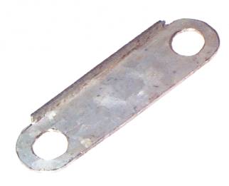
brake work. Idea # 2: Lipped Retention Plates: Palm used an idea stolen from the picture of the Terry's Jaguar Parts kit. Their idea is to use a locking plate with an edge folded down to prevent a bisected pair of retraction plate halves from rotating around the pivot pins. The fork halves cannot turn because they run into this lip. Palm fabricated such a locking plate -- but he didn't provide any locking tabs on it! Instead, he drilled the heads of the pins for locking wire (Palm has a drill press). This way, each time the assembly comes apart new lockwire can be used but the "lipped retention plate" can be reused over and over.
Here is a diagram for making this Bronze Fork
Retention Plate. It's presented as a PDF file so you
can easily print it out; if all goes well, it'll print actual
size. Make a pair of these plates out of some sheet steel
that the pivot pins can be tightened down onto without deforming
it. Precision isn't critical; you can see in the photo that
Palm's were handmade, and they worked fine. You can add
locking tabs to the design if you want. As mentioned above, another idea might be to simply purchase a
pair of the locking plates from Terry's
Jaguar. You might opt to simply cut the locking tabs
off and use lockwire to secure the pivot pins so you never have to
buy another pair of the locking plates. Assembling with these lipped retention plates requires
explanation. Obviously, cut your bronze forks in half;
cutting new bronze forks in half is recommended, as the
bronze tines get bent as the handbrake pads wear and can only get
bent back to the new position so many times before they just snap
off. Install the bronze fork halves first, making sure that
the tines of each half of the bronze fork are correctly inserted
into the holes in the handbrake caliper and that the handbrake
adjuster is backed out far enough that neither handbrake pad
contacts the disc. Position the plate on top of the bronze
fork halves with the lip positioned behind the split center
section of the bronze fork. Install the pivot pins (flat
washers are recommended to protect your homemade plate) finger
tight. With the parts so assembled, operate the lever on the
handbrake back and forth to get the adjuster to begin taking up
the slack and applying a load on the tines of the bronze fork
halves. As they get loaded, the bronze fork halves will try
to rotate around the pivot pins until they jam against the lip on
your retention plate. When the bronze fork halves have been
so loaded -- hopefully still without the pads contacting the rotor
-- tighten the pivot pins down securely and bend the locking tabs
or apply lockwire. Then continue to operate the handbrake
lever until the adjuster has taken up all the slack and the
handbrake pads are positioned very near the rotor. Check
that the tines on the bronze fork halves are pulling them a tiny
bit away from the rotor whenever the lever is released. Don't get carried away operating those handbrake levers by hand. Just get one click per swing. When really loose, it's possible to move it far enough to get two clicks, but it's also possible to get the clicker to pop out of place inside the adjuster -- meaning you'd have to take the thing back out and open it up again! You don't wanna do that, I'm sure.
Idea #3: Pinned Retraction Plate Halves: Brian Schreurs reviewed the assembly of a 6.0 litre TWR: "On this car, they sliced the fork in half and secured the halves by drilling small holes through the fork and into the caliper, and holding them down with cap screws." This is a good story, but it's not readily apparent how it would work. There is no underlying structure in the caliper to drill into; the area under the bronze fork between the pivot pins spans open air.
Here's an idea that will work, though: Make plates
of the same layout as the lipped
retention plate only without the lip, which makes it really
simple; it's just a straight flat piece of metal with two holes
drilled in it. Assemble the handbrakes with the tines of the
bronze forks engaged with the pads, but don't take up the slack in
the self-adjusters yet. Drill two holes through each plate,
one into each of the bronze fork halves. Use screws to
secure the fork halves to the plates. Make sure your screws
can't come loose. There are at least three ideas for those screws. First
idea: You could drill small holes and then take the plates
and bronze forks back apart, being careful to mark them so they go
back the same way. Tap the holes in the bronze forks and
enlarge the holes in the plates to fit the same size screws.
Put it all back together, using screws that have safety wire holes
in the heads. Safety wire these screws to the heads of the
pivot pins right next to them. Second idea: Drill holes sized for screws, say #6 or #8,
clear through plate and fork, being careful that your holes are
far enough away from the caliper to allow room for nuts.
Install screws with self-locking nuts on the back side. You
want all-metal self-locking nuts; things get too hot here for
nyloc inserts. Safety wire the two pivot pins to each other;
the self-locking nuts will ensure the smaller screws don't come
loose. This scheme has the advantage that the brakes don't
have to come back apart to drill and tap. The disadvantage
is you have to get those nuts onto the back side of the screws and
get a wrench on them to tighten them down. Or you could take
the handbrakes apart far enough to tighten the nuts down, then
reassemble. Third idea: Use pop rivets instead of screws. That
makes it really easy: Drill, pop, you're done. It
might be a good idea to use steel pop rivets instead of aluminum;
I dunno how the aluminum ones would hold up to the stresses
here. If you ever need to rebuild these brakes in the
future, just grind the heads off the rivets and reassemble with
new bronze forks and new rivets. The Redneck Solution: At least one vented rotor kit
omitted any parts necessary to fit the bronze forks to the widened
caliper. When asked why, they answered "It is presumed that
the owner will simply throw the handbrake calipers away."
Please don't be like that. Perhaps you've never experienced
a brake failure, but if you ever do it'll make a believer out of
you. |
|
| ||
 |
Improve your Jag-lovers experience with the Mozilla FireFox Browser!
©Jag-loversTM Ltd / JagWEBTM 1993 - 2024 All rights reserved. Jag-lovers is supported by JagWEBTM For Terms of Use and General Rules see our Disclaimer Use of the Jag-lovers logo or trademark name on sites other than Jag-lovers itself in a manner implying endorsement of commercial activities whatsoever is prohibited. Sections of this Web Site may publish members and visitors comments, opinion and photographs/images - Jag-lovers Ltd does not assume or have any responsibility or any liability for members comments or opinions, nor does it claim ownership or copyright of any material that belongs to the original poster including images. The word 'Jaguar' and the leaping cat device, whether used separately or in combination, are registered trademarks and are the property of Jaguar Cars, England. Some images may also be © Jaguar Cars. Mirroring or downloading of this site or the publication of material or any extracts therefrom in original or altered form from these pages onto other sites (including reproduction by any other Jaguar enthusiast sites) without express permission violates Jag-lovers Ltd copyright and is prohibited |
|