| ||||||||||||||||||||||||||||||||||||||
| ||||||||||||||||||||||||||||||||||||||
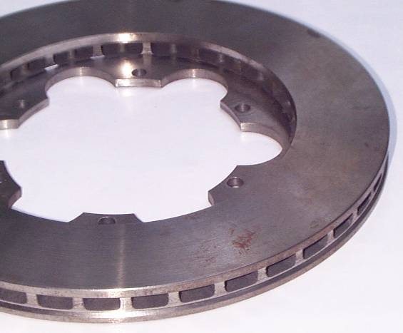
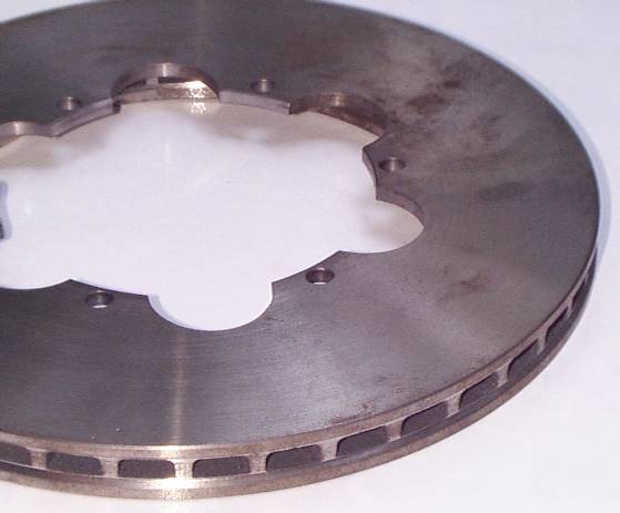
Jaguar XJInboard Rear Brake Upgrade(Replacing Solid Rotors w/ Vented Rotors)RotorsWhen Kirby Palm decided to assemble the parts necessary to install vented rotors on his '83 he decided to go with a layout very similar to Heartfield's TWR , but with a few detail differences. For one thing, the TWR centered the thicker rotor in the same place as the OEM rotor, meaning it grew 1/8" on each side. Hence, the mount bosses on the caliper had to be adjusted to move the inboard half of the caliper over 1/8" -- which is a completely different process on a Dana differential than on a Salisbury. Palm added the entire 1/4" of additional rotor thickness on the outboard side of the solid rotor location. This means the mounting of the inner half of the caliper does not require any adjustment -- which means the brake lines to it are unchanged and the handbrake cable attachments don't move. The spacer between caliper halves takes care of the location of the outer half. To accomplish this rotor location with a 3/4" thick disc, the 3/8" thick hub has a 1/8" recess machined into the inboard side, leaving the outer portion 1/4" thick. The 1/8" step will provide a suitable pilot diameter for securely centering the outer disc. Discs: You will need a pair of discs that look sorta
like these:
Wilwood calls their disc an "Ultralite 30 vane rotor", part number 160-3450. It's available from scads of suppliers online; just do a Google search for "Wilwood 160-3450" and pick the supplier offering the best price. Should you ever need to have discs custom made, here are the specs you need for ordering the discs:
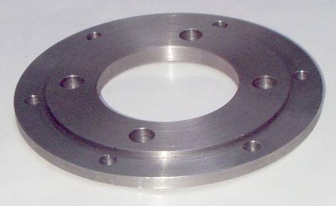
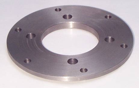
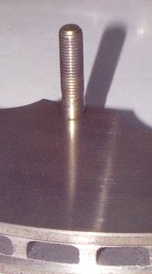
Coleman Racing offers a custom disc that'll work here. Note that brake disc suppliers will offer drilled or slotted upgrades to the basic vented disc. I recommend avoiding either of them. The optimum disc brake has a plain, unadulterated swept area, and any "gas vent" slots are cut in the pads rather than the disc. Under no circumstances should you ever drill a vented rotor, as the drilling screws up the venting. Slotted is the equivalent upgrade for a vented disc, but it invites cracks, accelerates pad wear, and doesn't really gain you any performance other than a miniscule weight reduction. The one upgrade you might consider is angled vanes -- as opposed to straight vanes -- but that involves keeping your left side rotor from getting confused with the right, costs more, and isn't really necessary here unless you're planning serious competition use. The basic vented disc is already a marked performance improvement over the OEM solid disc. Hubs: Palm had his hubs made at a local machine shop:
Hubs of two-piece rotors are commonly referred to as "hats" because that's what they normally look like, but this one is a simple flat plate with a 1/8" step machined into it. As mentioned previously, the design has since changed a bit. Here is the current design for the hub. It's presented as a PDF to be easier to print so you can hand it to your machinist. In fact, if the Microsoft gods are smiling on us today, it'll print actual size; be sure to set your printer to landscape paper orientation. Palm made his hubs out of steel, but you could opt to make your
hubs out of aluminum. Palm's machine shop claimed it
wouldn't make much difference in machining time or material
cost. Steel was chosen primarily because it wouldn't conduct
heat into the output shafts as readily. Sometimes you can convince your disc supplier to provide the hubs too. That's convenient, obviously, because they can make sure that hub and disc fit together properly before shipping them to you. Also, once they have the design on file, they can easily machine hubs for other XJ owners. Design Changes: Now, about the design changes since
Palm made this mod and took these pictures: The decision to go with the Wilwood rotors resulted in diameter
changes to the mounting bolt circle and the step diameter. The other change, obviously, is those two great big honkin'
access holes. Those evolved as follows: Brian Schreurs modified
Palm's design to add two 7/8" access holes on a 4-3/4" circle in
the hub similar to those found on OEM rotors used with Dana
differentials. The holes provide access to the two bolts
that hold the brake calipers to the Dana differential, and are
invaluable for removing the caliper without having to split the
caliper and remove the axle and rotor. Using a two-piece
rotor offers an alternative disassembly method involving removing
the rotor hub to get at those caliper mounting bolts, but it's
still a lot easier with the access holes! Rather than locate these access holes where they are on the OEM Dana rotors, however, Schreurs rotated them 90° around the hub. On the OEM rotor, the universal joint in the rear axle obstructs the access holes, so the axle must be unbolted first; this is no problem if you're rebuilding the entire rear suspension, but if your intention is merely to remove the brake calipers for service having to unbolt the axle is an unwelcome task. With Schreurs' access hole locations, the calipers are readily removed from the Dana differential without additional work. Then came yet another revision. It had been noted that Brembo aftermarket rotors all came with 7/8" access holes whether intended for use with Salisbury or Dana differentials, but the access holes in the discs for Salisbury diffs were located differently: They are on a 4" circle rather than a 4-3/4" circle. Brembo had actually incorporated an ingenious innovation. The access holes in their rotors intended for use with Salisbury differentials provide access to the five bolts that hold the output shaft bearing assembly in the differential itself. Note that the brake calipers are also attached to this output shaft bearing assembly. Hence, when (!) the output seals start leaking or the bearings need service, you can insert a socket through the rotor, remove the five bolts, and remove the entire output shaft assembly with the axle, brake rotor and calipers attached for servicing on the bench.Knowing a good idea when he sees one, Palm then revised the rotor
design to not only reflect Schreurs' improvements but also to add
two more access holes similar to those found on Brembo aftermarket
rotors intended for use on Salisbury differentials. To
facilitate having all four access holes in one hub design, the
disc-to-hub bolt circle was changed from six to eight bolts. But eight bolts won't work with the Wilwood rotors, and the holes
for the Salisbury were obstructed by the U-joint flange. So
Norman Lutz came up with the next innovation: Siamesing
those two sets of 7/8" access holes into a pair of oblong
holes. That brought the mount circle back to six
bolts. Then Palm replaced the oblong holes with 1-1/4" round
holes because they're simpler to machine. Here's why I'm explaining all this: Those two access holes
are perhaps the most difficult part for your machinist to deal
with, and they may affect his invoice accordingly. So,
clarifying your options: If you have a Dana differential (no
oil drain plug in the bottom), you really want access holes; trust
me on this. But you can, if you choose, just drill two 7/8"
holes on a 4-3/4" circle, which might be a bit easier for the
machinist. The only reason not to do this is that you may
eventually replace your diff with a Salisbury -- which is a
popular substitution since fitting a Salisbury is often a better
option than having to rebuild the Dana. If you already have
a Salisbury diff (has a drain plug in the bottom), access holes
are only a relatively minor convenience; you can easily get by
without them. Or, similarly, you can opt to drill two 7/8"
holes on a 4" circle. Don't worry about ever swapping in a
Dana diff; you won't be doing that. Note that, if you intend to actually use these access
holes, the scallops in the mounting flange of the rotor become a
necessity. If the flange is not scallopped, the disc will
obstruct the access holes. I don't think you'll find a rotor
without scallops, though; they're helpful for avoiding cracking
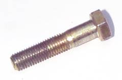
due to thermal stress, so all rotors will come scallopped. To be clear: Palm's original design worked just fine. The access holes just make servicing easier, and the diameter changes just allow the use of off-the-shelf Wilwood rotors. Bolts: You need bolts to hold these parts together. Grade 8 or alloy is a good idea here; this is not a good place to scrimp on cheap bolts, not so much due to load but rather due to the temperatures experienced. Now, really, you only need about 1" in length, because the mount flange on the disc is about 1/4" thick and the hub is also 1/4" thick, so a nut will neatly fit on a remaining 1/2". However, the joint between the disc and hub has a shear load on it, and when bolts are loaded in shear in this manner it is good engineering practice to use bolts with a smooth shank at the joint (note that Jaguar followed this policy on the input and output flange bolts on the differential). In this case, this means the bolts need to have a smooth shank longer than 1/4" but less than 1/2". Palm found 1-1/2" bolts that had a 3/8" long shank -- perfect. The fact that the threaded portion is 1/2" too long merely requires a little more time with a wrench.
Palm went with fine thread bolts, but coarse thread would also
work. Note: Due to the bolt circle diameter revision
to utilize the Wilwood rotors, alloy socket head bolts might be
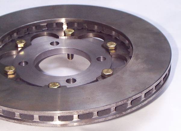
best here to ensure clearance under the handbrake mount bosses. When assembled, the rotor looks sorta like this:
On the inboard side, all hardware needs to be outside of a 4-5/8" circle, and nothing should protrude above the inboard friction surface.
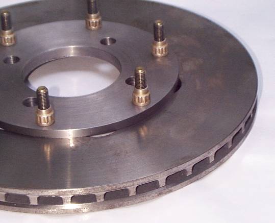
Those are military aircraft style 12-point silver-plated nuts. You're not likely to find nuts like those unless you have access to military hardware -- but any good quality all-metal self-locking nuts would work. You don't want to use nyloc nuts because the rotor might get too hot and melt the plastic inserts. On the outboard side, all hardware needs to be outside of the
same 4-5/8" diameter circle. The hub itself also needs to be
inside of a 6" diameter circle, because anything beyond that will
contact the inner boss for the handbrake caliper pivot pin on the
main caliper. Alternatively, you could make the OD of the
hubs a bit larger, like say 6-1/4", and grind 1/8" off the inner
handbrake boss on the outboard half of each caliper. That
would make the hub a bit stronger (perhaps good if you're making
yours out of aluminum) and shouldn't weaken the handbrake bosses
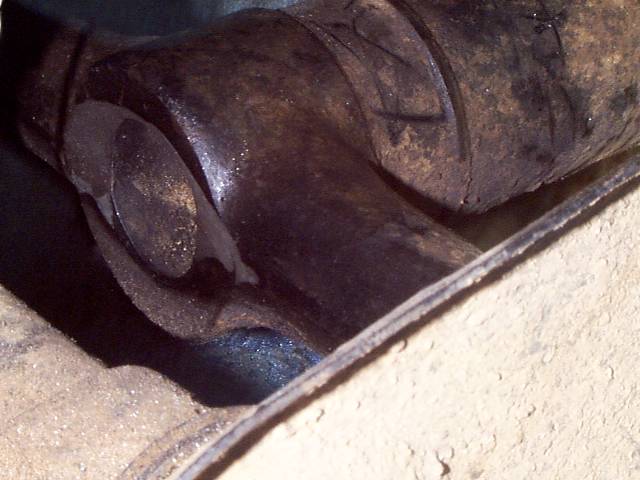
significantly. Anything that sits taller than regular bolt heads on the outboard side of the hub will interfere with the clamshell around the inner U-joint. To deal with the clamshell interference, you have several options:
2: You can turn the bolts around, putting the nuts on the inboard side. The bolts in these photos are too long for that side, but cutting them off would work fine since there's about 1/2" of space on the inboard side. You might need to do this anyway to use socket heads to clear the handbrake boss on the outboard side. 3: You can back the clamshell a bit outward on the axle. 4: The option Palm chose: relocate that clamshell to a cardboard box in the attic. The rotor mounting flange ID must be larger than 4-5/8" to clear the output shaft flange on the differential. In this next picture, a differential output shaft flange shim C33440 was placed on the inboard side of the rotor assembly to illustrate the clearance. The shim is not exactly the same shape as the differential output shaft flange, but it has the same OD.
As you can see, in Palm's design the shim sits on the inboard side of the hub itself, and there's about 1/16" of clearance to both the lugs on the disc and the bolt heads. The Wilwood configuration clears by even more. In a spectacular display of incompetence, the GT Jaguar kit caused interference here, and their solution was to instruct the installer to carefully grind on the output shafts on the differential to make their rotors fit. Fortunately, that company is long gone. Remember, the hub design has been revised to provide access holes; it doesn't look like the hub in this picture any more. The C33440 shims will obstruct those access holes. To make those access holes work as intended, you will need to cut scallops in the shims. Lay the shims on your hub, align them with some bolts, mark out where they need to be trimmed, and then cut them with tin snips or a Dremel. Lower Swingarm Clearance: Regardless of how you go about installing a wider rotor -- buying a kit or assembling your own parts -- the additional width will require a bit of grinding on the inner end of the lower swingarms. This is not really needed for clearance while together, but rather clearance for assembling. To install the brake rotor, the lower swingarm needs to swing down to nearly vertical to get it out of the way. When the wider rotor is installed, swinging the swingarm back up into place causes the center portion of the T on the swingarm to hit the outer edge of the disc. The necessary grinding becomes obvious at that point. Looking at the inner end of the swingarm, there is a hole into the tubular center portion of the swingarm. You need to grind an area that's roughly the shape of an eyelid, more above the centerline of that hole than below, and on both sides of the hole.
Fortunately, the lower swingarm on a Jaguar is strong enough for an armored assault vehicle, so this minor grinding won't even begin to threaten its structural integrity. Obviously, if you go with a disc thicker than 3/4", you will need
to grind more on the swingarm. Since there's not really any
good reason to go with a disc thicker than 3/4", don't. |
|
| ||
 |
Improve your Jag-lovers experience with the Mozilla FireFox Browser!
©Jag-loversTM Ltd / JagWEBTM 1993 - 2024 All rights reserved. Jag-lovers is supported by JagWEBTM For Terms of Use and General Rules see our Disclaimer Use of the Jag-lovers logo or trademark name on sites other than Jag-lovers itself in a manner implying endorsement of commercial activities whatsoever is prohibited. Sections of this Web Site may publish members and visitors comments, opinion and photographs/images - Jag-lovers Ltd does not assume or have any responsibility or any liability for members comments or opinions, nor does it claim ownership or copyright of any material that belongs to the original poster including images. The word 'Jaguar' and the leaping cat device, whether used separately or in combination, are registered trademarks and are the property of Jaguar Cars, England. Some images may also be © Jaguar Cars. Mirroring or downloading of this site or the publication of material or any extracts therefrom in original or altered form from these pages onto other sites (including reproduction by any other Jaguar enthusiast sites) without express permission violates Jag-lovers Ltd copyright and is prohibited |
|