| ||||||||||||||||||||||||||||||||||||||
| ||||||||||||||||||||||||||||||||||||||
|
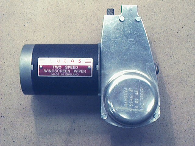
The Lucas DR1 Windscreen Wiper Motor There seems to be some confusion and also some misconceptions about how this windscreen wiper motor actually works. Also, questions have been raised about how it should be wired. If you want to know more, read on.
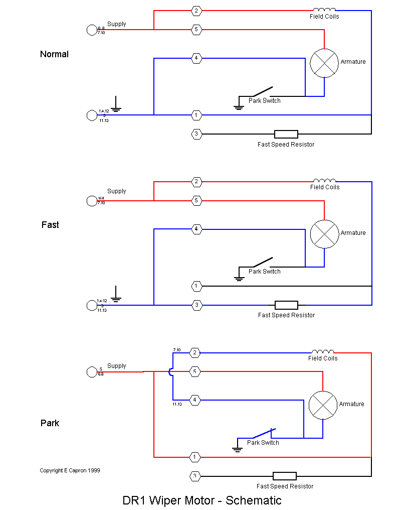
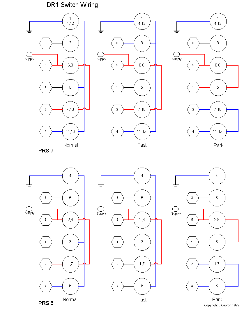
This motor was fitted to most XK 140s although it was eventually replaced by a later type, the DR3 which I believe was also fitted to XK150s. The correct body finish is in black crackle with the endplates in natural finish aluminium. Reproduction ID plates are available but the ones I have seen are silk screened onto aluminium and then anodised. The Lucas originals were etched and have a slightly different appearance. You can tell an original by running your finger nail across the surface. The etched letters are easy to feel. Internal electrical parts do not seem to be available apart from brushes. The motor armature is multi-pole and the magnetic field is generated from a field winding. The second, faster, speed is achieved by reducing the field current with a series resistor. A popular misconception is that the resistor is in circuit for the slower speed. This is incorrect. Reducing the field current reduces the magnetic flux. This has the effect of making the motor run faster but with reduced torque. The physical form of the resistor is a few turns of resistance wire would around the field coil. For 12 volt versions of this unit the speed control resistor is 12 - 14 ohms and the resistance of the field winding itself, approximately 8 ohms. Normal running current is about 3 amps. The motor is controlled by a three position switch. The positions being Park, Normal and Fast.Two types of switch were fitted designated PRS5 and PRS7. These can be easily identified because the PRS5 has 8 terminals and the PRS7 has 13 although terminals 2 & 9 are omitted. Terminals are numbered sequentially around the switch. The numbers are moulded into the plastic on the PRS7 - I am not sure about the PRS5. All the wires, 5 in total, go from the motor to the switch. If you remove the end cover from the motor the terminal connections 1- 5 are identified by very small cast-in numbers in the aluminium. At the motor, the wiring is terminated in small brass plugs that fit into sprung copper sockets. These are mounted on a Paxolin panel which is fragile and seems impossible to obtain as a spare part. Here is a simplified drawing of wiring in each of the three modes
In the all three modes a permanent supply is fed directly to the armature via motor connector 5. This supply is never switched although there is a thermally operated overload device within the motor housing. I have omitted this form the drawign to improve clarity. In Normal and in Fast, one side of the field coil is fed with a supply via motor connector 2. The return path from the armature and field winding is earthed via connectors 4 & 1 respectively in Normal mode. In Fast, the only difference is that the field earth return is via connector 3 which places the fast speed resistor in series with the winding. Once the motor is running forward the park switch is closed and therefore makes a second route to earth but the motor will run even if this is not made. When Park is selected several things happen. First of all the control switch removes the earth from connector 1 and changes it to a supply. Secondly, it removes the earth from the armature but that is still earthed via the park switch. Finally, the control switch connects 2 & 4 on the motor which has the effect of providing an earth to the non-supply side of the field coil. All earth returns ar now via the park switch and most importantly, the wiring to the field coil has been reversed. This makes the motor run backwards. In doing so, a mechanical arrangement in the gearbox causes the crosshead to change its position and when it reaches the appropriate point in the cycle it opens the park switch. The motor now stops because the only remaining earth has now been removed from the armature and the field winding. This is, obviously, the Park position and an adjustment is provided by turning a knob on the outside of the gearbox. Studying the diagram for the three modes will make clear what is going on. I have also included below the wiring for the control switch and by putting the two together you can see eactly how all this is achieved.
The colour coding for the wiring is not important as long as the correct motor terminals are connected to their appropriate switch pins but for completeness the original XK140 wiring is shown below. 1 = Green with Purple 2 = Black with Green 3 = White with Green 4 = Green with Blue 5 = Green
Although I have not been able to verify this it is highly likely that the same principle applies to the later DR3 motors. These have 6 connections as a permanent supply goes to the motor directly from the A4 fuse rather than from the control switch. It may well be that this was done to facilitate a different self parking arrangement. Perhaps someone could let me know. Reproduced with kind permission from Eric Capron's Homepage http://www.beaconsfield.demon.co.uk/index.html |
|
| ||
 |
Improve your Jag-lovers experience with the Mozilla FireFox Browser!
©Jag-loversTM Ltd / JagWEBTM 1993 - 2024 All rights reserved. Jag-lovers is supported by JagWEBTM For Terms of Use and General Rules see our Disclaimer Use of the Jag-lovers logo or trademark name on sites other than Jag-lovers itself in a manner implying endorsement of commercial activities whatsoever is prohibited. Sections of this Web Site may publish members and visitors comments, opinion and photographs/images - Jag-lovers Ltd does not assume or have any responsibility or any liability for members comments or opinions, nor does it claim ownership or copyright of any material that belongs to the original poster including images. The word 'Jaguar' and the leaping cat device, whether used separately or in combination, are registered trademarks and are the property of Jaguar Cars, England. Some images may also be © Jaguar Cars. Mirroring or downloading of this site or the publication of material or any extracts therefrom in original or altered form from these pages onto other sites (including reproduction by any other Jaguar enthusiast sites) without express permission violates Jag-lovers Ltd copyright and is prohibited |
|