Electric Fan Conversion

Electric Fan (e-fan) Conversion
Alex Cannara
The stock mechanical fan and clutch on the XJ6 will do a good job of keeping engine temperatures under control. Removing the stock items and installing an electric fan system will not solve overheating problems caused by things like a plugged radiator.
That said, the mechanical fan components do fail. The clutch can either cause the fan to freewheel at all times, or seize up, causing the fan to spin too fast. The former condition can obviously cause overheating problems in traffic. The latter can have somewhat catastophic consequences, especially on cars fitted with a plastic fan. The plastic fan is, over time, susceptible to cracking. Spin a cracked fan too quickly, and the resulting forces can cause the fan to fly apart, potentially damaging radiators, distributor caps, fan shrouds, hoses, and the bonnet. Driving with a cracked fan can be a very expensive proposition, not to mention the possibility of being stranded on the side of the road.
When faced with replacing your fan, many choose to stick with the factory items. Unfortunately, the OEM fan is relatively expensive (over USD 200). Some have used various aftermarket mechanical fans. Others, such as Alex Cannara, are strong supporters of converting to an electric fan system. The benefits are that it's a relatively inexpensive system, it's reasonably quiet, doesn't rob signifcant amounts of engine power, and can be configured to run even with the ignition off to minimize underbonnet heat build-up after parking.
There are of course, different vendors of electric fans and controllers, and many different ways to go about installing them. Here is Alex Cannara's guide to installing an e-fan (on the Series II, others similar). Click on any picture for a larger version.
-Chuck Renner
***
Cannara's Hayden electric fan and controller modification for the XJ6
Revised Oct 2002
Here are some steps to go with the pictures of our SII's mod (SIII is
very similar)...
Remove engine fan, clutch and upper and lower shrouds (SII). Keep one
upper-shroud angle bracket and all 1/4-28 bolts -- clean and repaint
bolts, or get new ones, preferably stainless. Buy some 1/4-28
nylon-insert locknuts and flat washers, all preferably stainless.
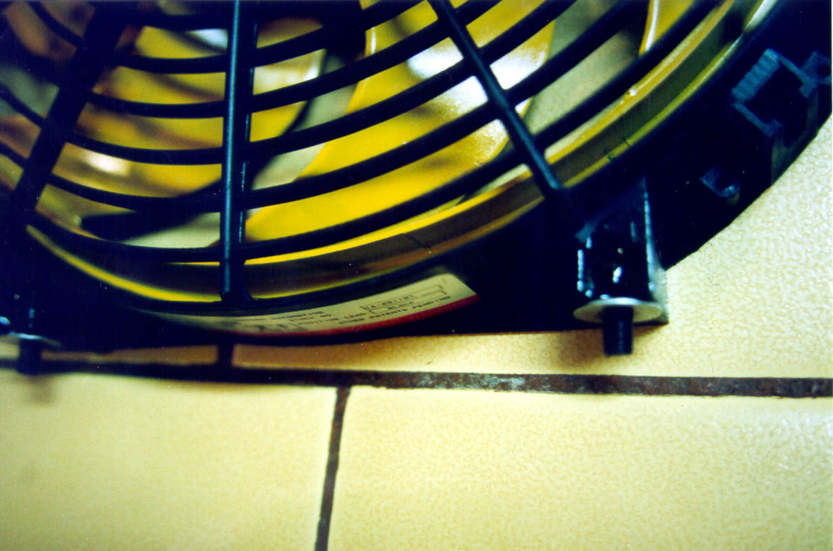
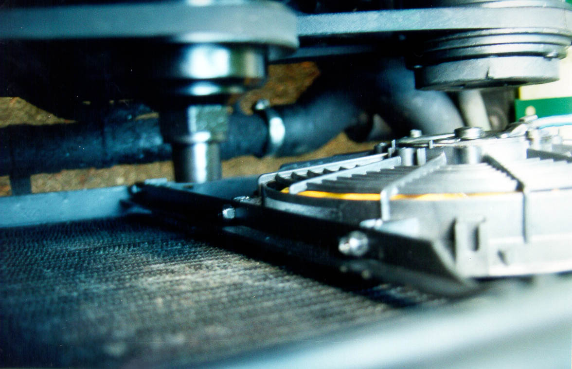
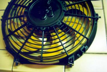
Choose the fan diameter and location(s) -- a 12" (#3680) will fit
nicely in front of the A/C compressor and can use the existing hole in
the radiator frame for its upper mount (using the saved angle bracket).
Larger fans (e.g., 3690, 14") may require more drilling of the upper
radiator frame, but may be needed in hotter climates. Two of the
smaller fans (12"), mounted diagonally, may be the best way to go
overall -- decide this before proceeding. Note that there's no
advantage to have the fans vertically overlap, thus both cooling the
same horizontal set of radiator tubes. Also, on an SIII, you might
want to have a fan cover the upper air passage above the radiator top
as well. The 12" fan draws only 7 Amps, the 14" about 9 and the 16"
one about 11 -- test before proceeding to be sure each works. As a
benchmark, the 14" fan delivers a very adequate 1000 cubic feet per
minute through a typical radiator. No shrouds are needed, so clearance
at the front of the engine becomes wonderful.
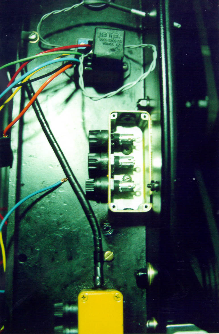
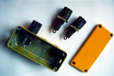
Get the #3647 controller and mount it via 2, 10-32 threaded holes in the
center (SII, one side for SIII) of the top frame over the radiator -- see
pictures. Use brass or stainless screws for mounting -- watch drilling
depth and screw length so as not to hit radiator itself (1/2" screws will
work fine).
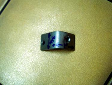
Clean 4, 1/4-28 bolts, mix some epoxy and press the bolts into selected
slotted mount receptacles on the fan housing, with epoxy under and
around them -- you may have to grind a little off opposite sides of the
bolt heads to get them to fit the mounting slots. Put a 1/4" flat
washer on the outside surface too -- see pictures. For the 12" fan in
front of the A/C, the mount slots used are: top, lower-left and both
right ones, as seen from engine side. Note that the fan blade may need
to be unbolted and reversed to push air toward the engine (I also
painted it yellow -- a fetish).
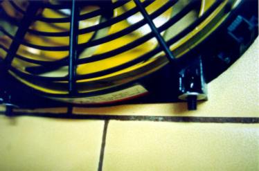
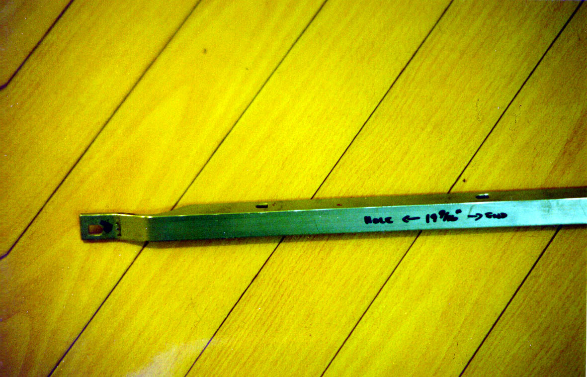
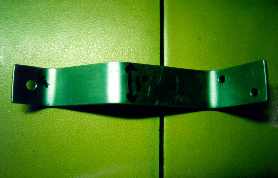
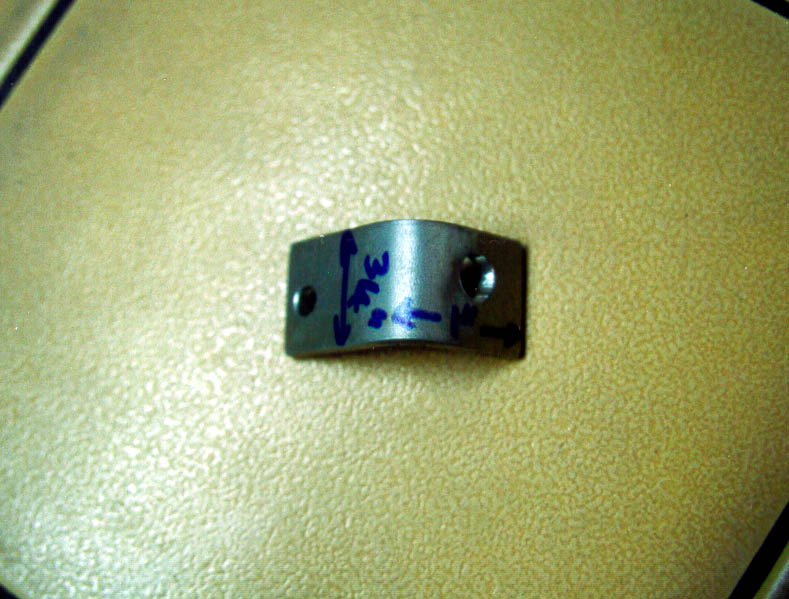
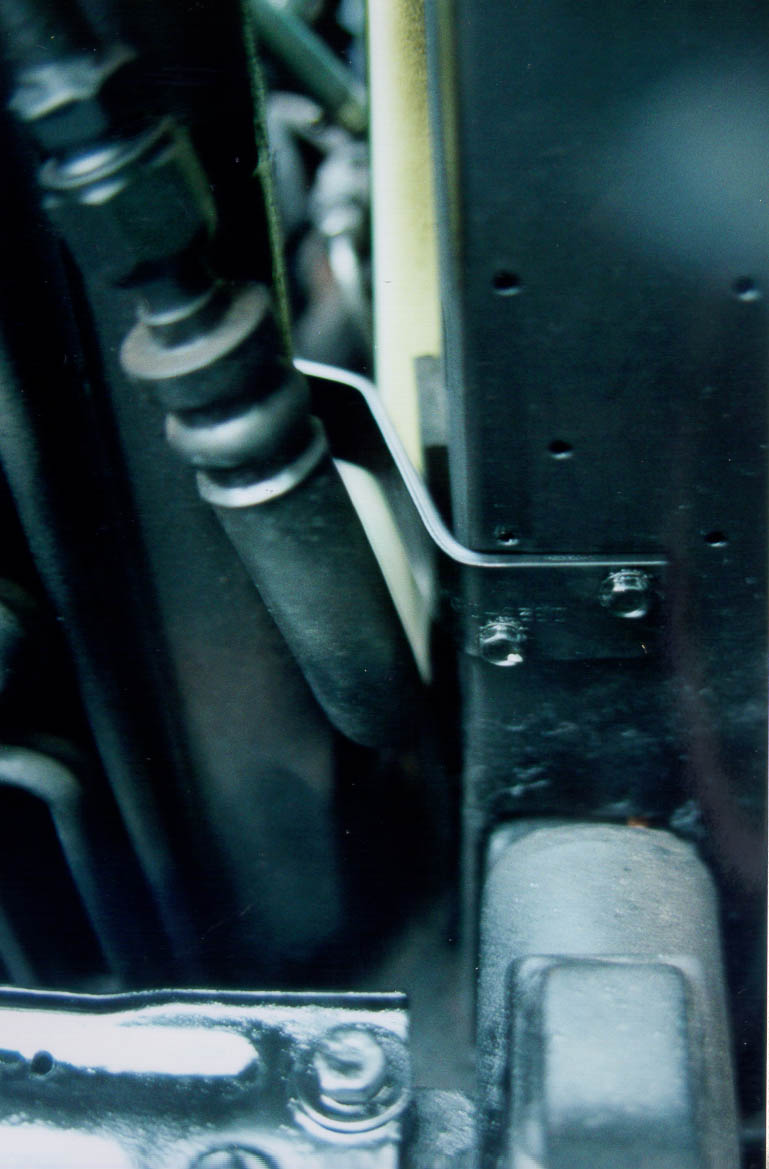
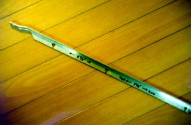
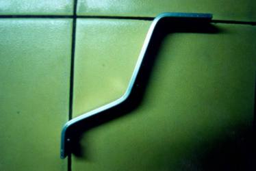
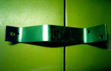
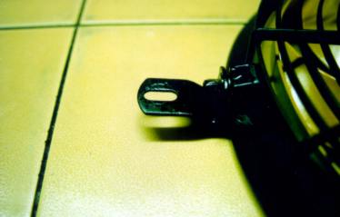
Make 2 aluminum brackets, per pictures. The vertical one is 3/4" x
1/8" angle stock, cut at top end to allow bending for proper
fan-radiator clearance (about 1/4"). The horizontal one is W shaped 1"
x 1/8" aluminum, bent so it can be screwed to the front of the frame
below where the hood latch mounts. The rear will be bolted to the
lower left fan mount. Drill appropriate holes in the brackets and
frame -- using the 12" fan also allows using the slotted hole in the
lower radiator frame for the vertical bracket's lower mount. If you
don't bend the lower end of the vertical bracket to meet that point,
make a third bracket out of angle or flat stock for the bottom end --
see picture. When the epoxy dries, the brackets and fan can be test
aligned and any adjustments to holes in them or the radiator frame
made. Note that the old upper angle bracket needs to be bent so its
lower portion goes a short way forward and under the radiator frame, to
match the alignment and spacing of the fan from the radiator's rear
surface. The W bracket's frame mount is by self-tapping screws into
the front of the side frame, so the bonnet may need to be removed.
Mount any second fan in a similar way, but on the lower right of the
radiator, as seen from the engine.

Optionally, degrease and paint all metal parts black. Mount the fan
and bring its ground wire to a good point on the frame, such as a
mounting bolt for the bonnet latch. Bring the blue wire up through the
grommet by the headlamp relay (SII) and over toward the controller.
Solder a ground lug to the controller's black wire and put it under the
nut holding the top end of the vertical bracket to the radiator frame
-- clean to bare metal on the frame and use a locknut, lockwasher and
oil. Both ground wires should have soldered lugs and be mounted on
lockwashers on bare, oiled surfaces. Do the same for any second fan.
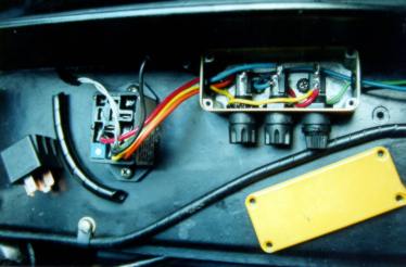
Now make a fusebox for 3 Littelfuse or Buss 3AG holders (see pictures).
This is also mounted via two screws into 10-32 threaded holes in the
radiator top frame. Drill holes for a 1/2" grommet at the controller
end and a 3/8" one at the other. The fuseholders should face forward.
Mount the box with some sealing grease underneath, using brass or
stainless screws.
Feed the orange, blue, red, yellow and green wires from the controller
into the box via the big grommet and solder the orange wire to the fuse
(end contact) nearest the controller, the blue one to the next holder,
and the red and yellow to the last (but to its side contact). Bring
the blue wire(s) from the fan(s) into the box via the 3/8" grommet and
solder to the side terminal of the fuse with the blue wire on its end
contact. Bring the green wire through the box and out (making no
contact) and down through the grommet the blue wire came up through --
the green wire is optionally available for connecting to the green A/C
clutch wire. Wrap the green wire in a neat bundle and tie-wrap it to
the A/C hose or something. Use a red or brown #12 or #14 stranded wire
and put a solder lug on one end that will fit on the alternator's power
bolt (or to the stud on the firewall). Add some shrink tubing to the
bare neck of the lug. Pull this wire up through the same path the blue
fan wire took and solder it to the end contact on the fuse holder with
the red and yellow wires. Put a 20Amp fuse in that holder and 10Amp
ones in the other two -- you'll use the latter to feed one or two fans.
Put spiral wrap around the wiring to and from the fuse box (see
pictures).

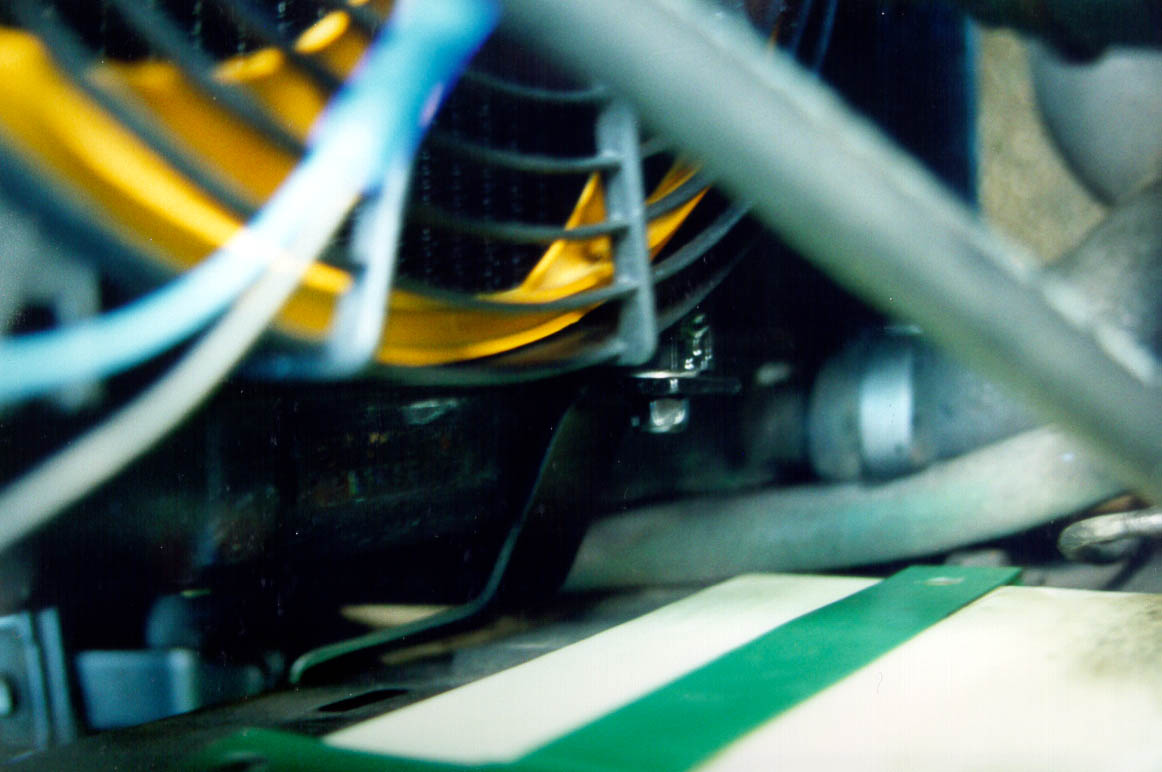
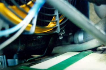
Drill a hole for a 3/8" grommet in the vertical part of the upper radiator
frame (see picture), insert grommet and pass the sensor probe though it and
over toward the inlet portion of the radiator. Coat the probe with
silicone grease and carefully jam it between some radiator fins an inch or
so down from the top of the radiator and in from the inlet hose -- it
should be under the air-intake passage (SII). Put spiral wrap around the
sensor wire and back through the grommet. Use a mounting clamp to hold the
wire (can use the same screw and captive nylon insert that was used for
that side of the SII's upper shroud). Tie wraps can be used as well.
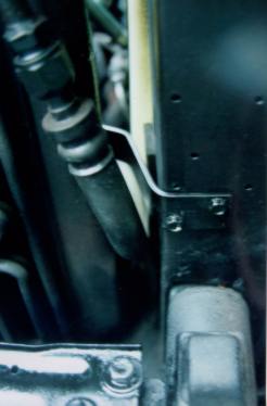
Connect the red or brown wire with the solder lug to the alternator's
power bolt (under A/C compressor), or all the way back to the firewall
stud, using tie wraps or clamps as necessary for neatness and safety.
Clean the power bolt as necessary, maybe change to brass nuts &
washers, and oil before tightening. Be sure the controller's relay
and fuses are in place. Start the engine and drive or idle the car
until warm -- the fan may come on. If not, turn the little white
screw on the controller clockwise (lower temps) until the fan comes
on. The desired setting is such that it comes on before the aux fans
(only one aux on SIII) do, but not before the engine reaches proper
temp. A second fan can be added, if necessary, by grounding its black
wire and bringing its power lead up to the side lug of the fuse with
the orange wire. Note that the fan(s) may often come on after
parking, because the latent heat in the engine can raise the
radiator's temp via thermal siphoning, even when no longer moving.
This is good. You're cool.

Another feature can be added -- a diode from the Aux-fan relay to the
fan power for one or both new fans. This will provide a fail-safe
system, should the Hayden controller fail. Ideally, two diodes, one
from the controller to the fuse for that fan, plus one to the same
spot, but from the Aux relay. The two cathodes (banded ends) should
connect to the fan fuse. It's likely best to feed the fan in front of
the A/C and exhaust this way. Now you're cool and confident!

|