| ||||||||||||||||||||||||||||||||||||||
| ||||||||||||||||||||||||||||||||||||||
|
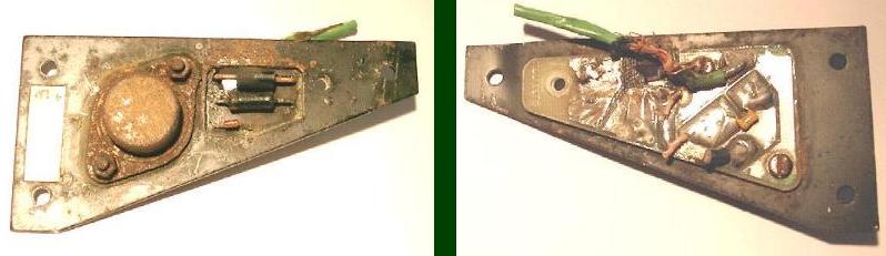
This article concerns the Delanair MK3 climate control unit as fitted to my 1988 XJ-S, it may also apply to other years, and is reputed to be used in some versions of the XJ40 (XJ6) saloon. At this stage, I shall point out that although the information provided here is done so in good faith, I shall not be responsible for any consequences arising from actions taken by others to which I have no control. The Delanair Mk3 system has a known problem of failure. The centrifugal blowers on both sides need to run in unison at a computer-programmed speed to enable the system to operate correctly. If one blower fails, the system can sound quite normal although the amount of air forced through the system will be much less. With both fans blowing at high speed, it should be quite forceful. The fuses for the fans are in the main fuse-boards on each side. Pull the fuse on each side in turn and see if the other blower is operating correctly. The speed should vary automatically in any speed position other then MAX, reducing as the selected temperature is achieved. Selecting MAX, energizes the 'high speed' relay which bypasses the Darlington transistor. When first turned on, the blowers should pulse, this is the air conditioning computer powering-up. After this, if either blower runs on fast speed continually or fails to run at all, there is a problem! The blower on each side contains a solid state speed control circuit comprising of a Darlington power transistor, resistor, two diodes, a capacitor and a relay for high speed fan operation. One of my blowers had failed and after removing the assembly, I found that the circuit board had burnt out. The photograph below shows the mess that remained. Of course, the circuit board cannot be bought separately and a new blower assembly is very expensive, but as I will show here, it can be re-built quite easily. To remove the blowers, disconnect the battery and remove the lower scuttle and either glove box or speedometer panel depending upon which side is being worked on. The fuse box needs to be unbolted and swung to one side but does not need to be disconnected. A vacuum line is connected to the re-circulation servo that can be simply pulled off. The blower is held in place by two bolts, one is obvious but the other is fairly high up and needs a socket on an extension, ideally with a universal joint. A blue plastic air duct connects the blower to the centre console, which can be removed. The passenger side will have an off take to feed air to the in-car sensor venturi. At this point, the blower will be held in place by a flap at the rear, which allows fresh air in. By holding the re-circulation flap open against its spring pressure, the fresh air flap will close and the blower will eventually come free, allowing the wiring to be disconnected. Once the blower unit is out it can be dismantled, revealing the motor, relay and electronic circuit board. One side also has the ambient temperature sensor attached to the blower casing. While the blower is out, the black plastic tubes attached to the air conditioning unit can be removed by twisting and pulling. This allows access into the unit to clean out any debris that may be blocking the condensate drain.
The left hand photograph shows the side of the circuit board exposed to the cooling air within the fan housing, The large round steel capsule is the Darlington power transistor, the small red diode is the one which commonly corrodes away due to being within the moist air stream. The other two black items are the resistor (lower) and its diode (upper). These protect the Darlington by clamping the voltage to that of the supply. There may be more then one build of board resulting in changes to how the components are mounted, but the schematic wiring diagram which can be followed, especially if you are unable to identify the painted line, (cathode) on the diodes. The right hand photograph shows the wiring connection side, the yellow capacitor can be seen, as well as in my example, the hole in the circuit board caused by the electrical short. Under normal circumstances the faulty components can just be replaced by soldering, normally the Darlington and the small diode. The Darlington case is insulated from the blower casing with a gasket and plastic bushes, its screws need to be in good condition as they provide an electrical path to the circuit board. In my example the whole board needed replacing. The Darlington case needs to be in the air stream for cooling purposes, and in my design, so is the resistor, but this is more for convenience. I mounted the two new diodes on the other side away from the moist air stream, the small glass diode being replaced with a larger, more robust item. The relay in my example was working fine, but please check yours whilst it is out and replace it if there is any doubt. It is located within the blower housing and will be covered in grime! While you are in there, inspect the motor, clean, lightly lubricate, test and if necessary replace the carbon brushes.
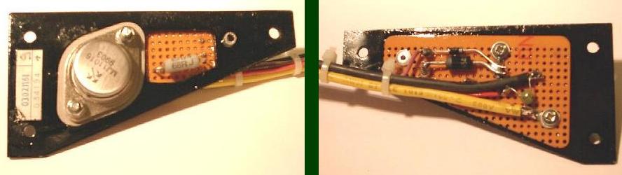
These photograph show my re-built board. Points to note, are that the holes in the breadboard and all components were 'sealed' with non-conducting varnish to prevent air loss and corrosion and that the colours of the wiring has changed (I didn't have any of the right colour in the cable size required to hand!). The second blower on my car was blowing at high speed whatever the setting, this side was much simpler, as all the other items were fine I just replaced the Darlington and small diode. As the motor 'earths' through the Darlington, one failure mode is to fail closed circuit, so the relay is often incorrectly blamed! Darlington Information The original is made by TI with the designation 2N6284 Its specifications are: - Continuous collector current Ic (max) = 20A Collector emitter voltage Vceo (min) = 100v Current gain hfe (min) = 750 @ 10A Power Pd (max) = 160w Case style TO3 Any NPN Darlington power transistor with the same or better ratings would do the job, The one I used was a MJ11016 made by STM, which has a slightly higher specification. (30Amp) Parts list The components should be available at any good electronic store, I have an account with RS Components so I bought mine there, the part numbers and costs (as at August 2000) were: 295-179 Darlington MJ11016 - Ł3.61 151-776 2.5W 68ohm Resistor - 29p 829-586 0.01uF Capacitor - 3p 261-299 IN5401 Diode - 2p 261-176 IN4004 Diode - 8p 298-437 Transistor mounting kit - Ł1.78 298-493 Screw kit - Ł1.26 It should be noted that these prices do not include VAT and that some of the parts have a minimum order of 10 items, such as the diodes, but they are cheap, and you will need to do the other blower soon enough. I already had the wiring, breadboard, paint, rivets and varnish etc left over from a previous project. The actual colour of the wiring may vary depending upon which side blower you are working on. What really matters is that you take note of what you have in your car and connect everything back as the diagram shows. Relay details Described as a 'High-speed' relay, its actually a normal relay, its purpose is to by-pass the Darlington, providing full blower speed. Its a Hella 4RA, blue in colour. Terminals 30 and 87 are the switch contacts, 85 is the neutral and 86 is the line in to power the relay. As there is a diode built into the relay, be careful to ensure correct polarity when bench testing! Schematic wiring diagram
As a postscript, boy does this make a difference! I've had this Jaguar for nearly three years and put up with having either the (single) blower going full blast or being completely off and suffering a very stuffy interior. Links Mark Barker has a great web site covering many aspects of the Delanair climate control system. I do recommend that you visit his site as it covers many interesting aspects of this system. Kirby Palm's 'The Book' A must for anyone who owns, or is considering buying an XJ-S Comments, corrections etc? Send
me an Email |
|
| ||
 |
Improve your Jag-lovers experience with the Mozilla FireFox Browser!
©Jag-loversTM Ltd / JagWEBTM 1993 - 2024 All rights reserved. Jag-lovers is supported by JagWEBTM For Terms of Use and General Rules see our Disclaimer Use of the Jag-lovers logo or trademark name on sites other than Jag-lovers itself in a manner implying endorsement of commercial activities whatsoever is prohibited. Sections of this Web Site may publish members and visitors comments, opinion and photographs/images - Jag-lovers Ltd does not assume or have any responsibility or any liability for members comments or opinions, nor does it claim ownership or copyright of any material that belongs to the original poster including images. The word 'Jaguar' and the leaping cat device, whether used separately or in combination, are registered trademarks and are the property of Jaguar Cars, England. Some images may also be © Jaguar Cars. Mirroring or downloading of this site or the publication of material or any extracts therefrom in original or altered form from these pages onto other sites (including reproduction by any other Jaguar enthusiast sites) without express permission violates Jag-lovers Ltd copyright and is prohibited |
|