|
11.1 - Fuses and Relays ( ,
)
Fuses are contained in 5 main fuse boxes as listed below. The descriptions are from the Jaguar handbook and aren’t always the clearest. When diagnosing a problem, bear in mind that several fuses may be involve in getting a particular component to function ( eg power feed, control relay feed, electronic control module feed ), so do check the full list.
Engine Bay Left |
|
|
F1 |
25 |
Heated Front Screen
– Right Side |
F2 |
10 |
Main beam headlamp
– Left side |
F3 |
25 |
Starter Solenoid |
F4 |
10 |
Dip beam headlamp
– Left side |
F5 |
10 |
Side light, indicator
and repeater – Left side |
F6 |
20 |
Windscreen wiper |
F7 |
|
Unused |
F8 |
15 |
Air conditioning
water pump |
F9 |
|
Unused |
F10 |
10 |
Horn 1 |
F11 |
30 |
Engine Cooling fans
– series & parallel modes |
F12 |
|
Unused |
F13 |
|
Unused |
F14 |
10 |
Horn 2 |
F15 |
25 |
Heated Front Screen
– Left Side |
F16 |
|
Unused |
F17 |
30 |
Engine Cooling fans
– series mode |
F18 |
10 |
Front Fog lamp –
Left side |
|
|
|
Engine Bay Right |
|
|
F1 |
|
Unused |
F2 |
10 |
Main beam headlamp
– Right side |
F3 |
|
Unused |
F4 |
10 |
Dip beam headlamp
– Right side |
F5 |
10 |
Side light, indicator
and repeater – Right side |
F6 |
5 |
Engine ECU |
F7 |
25 |
Air pump ( 6 cyl
) Ignition coils ( 12 cyl ) |
F8 |
10 |
Air con clutch (
note separate inline fuse ) |
F9 |
|
Unused |
F10 |
5 |
Alternator, Lighting
control module – Right side, Air con clutch, windscreen &
headlamp wash heaters |
F11 |
20 |
Engine ECU relay
supply, injectors |
F12 |
10 |
Engine ECU, Starter
Relay, ignition coil sensing and air pump ( 6 cyl ), injection
relay and ECU sensors ( 12 cyl ) |
F13 |
10 |
Windscreen washer
pump |
F14 |
10 |
Oxy sensor heaters,
idle speed control valve |
F15 |
|
Unused |
F16 |
10 |
Air pump control,
Vacuum valve ( 12 cyl ), intercooler water pump ( 6 cyl supercharged
) |
F17 |
30 |
Headlamp power wash
pup |
F18 |
10 |
Front fog lamp –
Right side |
|
|
|
Rear Seat Heelboard
– Left Side |
|
|
F1 |
|
Unused |
F2 |
10 |
Heated Door Mirrors,
Instrument Illumination |
F3 |
15 |
Seat motors –
Right side |
F4 |
15 |
Seat motors –
Right side |
F5 |
10 |
Instruments |
F6 |
5 |
Seat ECM, low power
door switches, mirror motors |
F7 |
30 |
ABS pump |
F8 |
|
Unused |
F9 |
20 |
Cigar lighters |
F10 |
5 |
Cruise control |
F11 |
20 |
Heater blower –
left side |
F12 |
5 |
Instruments |
F13 |
15 |
Steering Column
motors |
F14 |
10 |
Auto transmission
ignition switched supply |
F15 |
30 |
Window motors –
left side |
F16 |
5 |
ABS ignition switched
supply |
F17 |
|
Unused |
F18 |
10 |
Air Con supply |
|
|
|
Rear Seat Heelboard
– Right Side |
|
|
F1 |
15 |
Central Locking |
F2 |
5 |
Gearshift interlock,
Centre console switches, interior lighting switch |
F3 |
15 |
Seat motors –
left side |
F4 |
15 |
Seat motors –
left side |
F5 |
5 |
Auto transmission
ECU |
F6 |
|
Unused |
F7 |
30 |
ABS Control |
F8 |
10 |
Interior lights,
boot lights |
F9 |
25 |
Seat heaters |
F10 |
5 |
Diagnostic system,
Fuel pump relay coil |
F11 |
20 |
Heater blower –
Right side |
F12 |
10 |
Air con, Seat ECM,
Mirror heater relay, Power steering |
F13 |
|
Unused |
F14 |
10 |
Mirrors, heater
rear window, cigar lighter, rear lighting control |
F15 |
30 |
Windows – Right
side |
F16 |
10 |
Windscreen wipers,
Front screen heater control, Front lighting control – left
side, water pump relay, headlamp levelling, clock |
F17 |
15 |
Airbag |
F18 |
15 |
Sunroof |
|
|
|
Battery Compartment |
|
|
F1 |
25 |
Stereo |
F2 |
5 |
Tail and plate lights
– left side |
F3 |
15 |
Reverse lights,
stop and indicator light – left side |
F4 |
10 |
Security system |
F5 |
10 |
Main CPU |
F6 |
5 |
Diagnostic system,
phone |
F7 |
30 |
Fuel pump |
F8 |
15 |
Boot release, aerial,
stereo unswitched feed |
F9 |
15 |
Rear fog lights,
stop and indicator light – right side |
F10 |
5 |
Stereo control relay |
F11 |
25 |
Towing module |
F12 |
5 |
Phone and accessory
relay |
F13 |
10 |
Accessories |
F14 |
|
Unused |
F15 |
25 |
Heated rear window |
F16 |
5 |
Airbag warning |
F17 |
|
Unused |
F18 |
5 |
Tail and plate light
– right side |
|
|
|
11.10 - Sound System ( ,
)
11.10.1 - Radio Wiring ( ,
)
The purple/orange wire in the radio wiring harness will mute the radio when grounded. It can be directly connected to the yellow wire of a Nokia car kit for automatic mute when the phone is in use.
11.10.2 - Radio Aerial/Antenna Replacement ( ,
)
These seem to be a commonly failing item. The wiring connector was changed during the lifetime of the car, so ensure you get the right one when replacing.
When replacing, lift it slightly up at the bottom and then slide it down over the window button.
11.10.3 - Radio Aerial/Antenna Maintenance ( ,
)
Periodically wipe the raised antenna with a damp cloth in an upward direction, which avoids pushing dirt into the mechanism. Switch-cleaner is preferable to WD40 as a cleaning agent, as it does not leave a sticky residue behind.
The standard radio unit will periodically display a message requesting that the aerial mast or cassette unit be cleaned. This is a useful reminder, but more frequent cleaning, particularly in dirty road and weather conditions, may be advisable.
11.10.4 - Radio Connections, CD Player and Cartridge Removal ( ,
)
The standard radio has an 8 pin DIN style socket for attaching the CD stacker, which is wired through into the boot. Where no factory CD player is fitted, the Alpine CHM620 can be fitted using the existing wiring and will be controlled from the standard head unit.
The stereo also has a 5 pin DIN socket for connecting a separate power amplifier, available in some markets to drive a sub-woofer.
In addition, there is the main 20 pin connector to the stereo, with pins 1 - 10 on top going right to left and pins 11 - 20 on the bottom. 1 and 10 are 12V feeds, 4 switches the lighting on and off and 3 is a variable feed from the lighting dimmer circuit.
If the CD cartridge appears to be stuck, try pushing a credit card or similar under the cartridge to the right of the eject button.
11.11 - LCD Clock ( ,
)
Clock modules occasionally suffer from faint displays, caused by bad contacts between a circuit board and flexible ribbon cable inside the unit. It is possible to make a repair, though some may consider it to be a less than professional fix!
Access can be gained following the instructions in section 10.1. Remove the connector at the rear of the clock unit itself, undo the four screws attaching it to the rest of the assembly and then take it to a bench area for further work.
The unit itself is opened by undoing the small screws at the rear and releasing the plastic tabs. Whilst the unit is open, take care not to lose any of the small components in there. Release the LCD panel itself by carefully spreading the black tabs holding it into the white plastic bracket. The panel is attached to the main circuit board by a ribbon cable, and it is the connection at the circuit board end that is the problem.
Tape the ribbon cable in place and use a business card or piece of pizza box ( both have been successfully deployed! ) to put pressure on the ribbon cable where it connects to the pcb, behind the white plastic bracket.
Take the unit to the car in plug it in. Use the time set buttons to cycle through all the digits to make sure the fix is complete before reassembly. If segments are still missing or faint, additional pressure may be needed on the ribbon cable.
When all is working, reassemble the clock unit and then refit into the centre console. Attach the cable and take care not to stress any other wires as you fit the console back into position.
11.12 - Memory Seats and Steering Wheel ( ,
)
Some models are fitted with the memory seat, steering wheel and mirrors functionality. The ECU's associate the position of the various devices with a particular key fob and adjust them accordingly.
The motors, particularly for the steering wheel, are known to fail and replacement has been the only solution reported. In some cases, the system appears to become inactive, which can be overcome by disconnecting the battery for an hour or so.
11.13 - External Temperature Sensors ( ,
)
These are located in the brake cooling ducts, behind the front bumper and in front of the wheelarch liner. Access can be obtained by removing the front undertray.
The left hand sensor is used as input to the climate control system. The right hand sensor is used to control the washer reservoir heater and washer jet heaters, active below 4C, and to control the heated seats, active below 26C.
11.14 - High Level Brakelight ( ,
)
Where fitted, this is driven from the relay located in the red, right hand socket in the boot fuse box. The relay is identical to the two others adjacent.
11.15 - Front Indicator Bulb Replacement ( ,
)
The manual indicates a special tool is required to remove the indicator unit from the front bumper. The tool is flat plastic blade, and can therefore be improvised yourself. You can use metal if you are careful to protect the finish on the bumper.
The blade slots into a gap on the inboard side of the indicator unit and releases an internal catch by pushing it to the outboard side of the car.
Bulb replacement and refitting the unit and then straightforward.
11.16 - Sports / Normal Switch Light Replacement ( ,
)
|
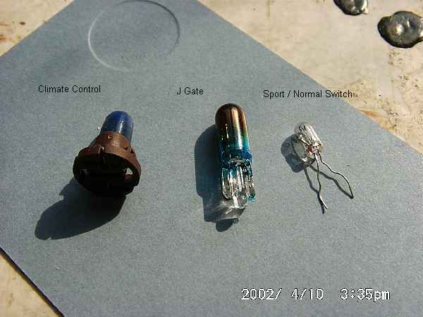
Jaguar does not offer a replacement bulb, but insists you replace the switch. However, replacement is straightforward with a sub-miniature bulb as sold in electronics shops.
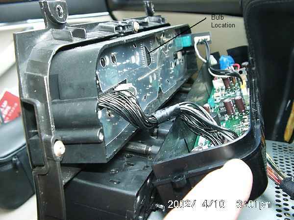
To gain access to the switch, remove the ashtray and plastic transmission selector surround (see section 10.1 of this guide).
Using a small screwdriver, release the clear plastic lugs holding the lower part of the switch into the black upper casing and remove the lower part of the switch. The bulb sits inside a small piece of rubber which itself sits on two metal prongs which carry the current to the bulb. The wires from the bulb go back up through the rubber in the same holes as the mounting prongs.
Remove the blue cap from the bulb then pull the rubber mount off the prongs. Gently pull the bulb wires through to the lower side of the rubber, straighten them, then lift the bulb out of the rubber from the top.
To refit, put the new bulb in, making sure the wires go through the two tiny holes in the rubber mount underneath the bulb. Bend the wire round and up inside the mounting holes, then push the rubber back down onto the prongs. Make sure the switch position is the same on upper and lower halves of the switch, then click the lower assembly into the upper casing.
Reattached the wiring and refit the plastic transmission surround and ashtray.
|


