|
1 - Introduction ( Paul Stow,
December 1, 2001
)
The X300 was introduced in 1995, as the latest in a distinguished line of cars branded the Jaguar XJ6. In addition to the base model, Sovereign, Vanden Plas and Daimler models were made available in varying markets and with increasing levels of trim and equipment. The car was available with 3.2l or 4.0l engines and, in the top of the range XJR model, a 4.0 supercharged variant.
Jaguar had enjoyed increasing success with the previous XJ40 model, which since it’s introduction in 1987 had undergone a number of updates and continuously increasing production and quality. The X300 was to build on this success, and formed the platform with which Jaguar re-emerged as a leader in reliability and customer satisfaction, forcing rivals from Germany and Japan to sit up and take notice.
To many people, the curves of the X300 body shape were reminiscent of earlier XJ6 models as opposed to the more square lines of the XJ40. The overall proportions are similar, however, with the elegant lines matched by limited rear legroom and a shallow boot caused by locating the spare wheel and battery under it's floor.
The interior of the X300 is immediately familiar to XJ40 lovers, with the central 'ski-slope', J-gate transmission selector, and 6 gauge instrument binnacle. Closer examination, however, shows many detail improvements to stereo and air conditioning systems, revised panelling, door seals etc etc.
Under the bonnet, the basic layout is again familiar with the AJ16 engine being the last in a long line of six cylinder, double overhead cam, 24 valve engines from Jaguar, stretching back to the Le Mans winning C-types of the 50’s. Like the interiors, however, the AJ16 contains a host of detail improvements, the most visible of which is the replacement of conventional coil and distributor ignition by an individual coil on plug arrangement, eliminating the need for HT leads.
For the first time on a modern Jaguar, the XJR model added an Eaton type supercharger to the 4.0l engine, increasing power to 316bhp - more than available from the 6.0l V12. To handle this power, the XJR shared the GM gearbox with the V12, had stiffened suspension to provide a sportier feel to the car,and a distinguishing mesh style front grill.
1.1 - VIN Numbers and Year of Manufacture ( Paul Stow,
December 1, 2001
)
1995MY From 720125
1995.5 From 739427
1995.75 From 746613
1995.75 LWB From 746814
1996MY From754304
1997MY From 787954 to 812255
1.2 - About the Guide ( Paul Stow,
December 10, 2001
)
This guide is based on a '95 UK Spec XJR, and so details will differ from differently specified models. In particular, other engine specifications will not have the supercharger and intercooler, and US spec models will have additional emissions equipment such as EGR ( Exhaust Gas Recirculation ).
Some of the less common tasks are omitted, on the basis that the author and list have no experience of them yet! This also hopefully means that the vast majority of X300 owners won’t need to know about them either. However, if you think something should be included then please let us know.
10 - Bodywork and Interior ( ,
)
The X300 bodywork and underbody are generally free from rust and other vices. The interior is also well put together and not prone to rattles and squeaks. To maintain this condition, care should be taken to ensure cable runs and fittings are correctly reinstalled and any tie-wraps or other fixings replaced before reassembly is completed.
10.1 - Access to Centre-Console - Ski-Slope Removal ( ,
)

|
Open the ashtray, remove the lighter and internal bin and undo the two screws at the rear. Remove the ashtray itself, disconnecting the electrical connection to the lighter as you do so.
Feel into the hole and forward under the centre wooden trim. There are two nylon wing-nuts, upside-down, holding the wood in position. Undo them.
Remove the plastic transmission selector surround by squeezing gently on the sides to release the clip fixings - two on each side. Lift the plastic and disconnect the Sport/Normal switch wiring.
Remove the chrome / leather selector surround, again by squeezing gently. This time the fixings are at the front left, front right and rear middle of the surround and it is often best to start with the one at the rear. It can be a little tricky and frustrating, but it will finally release so try not to force it.
From the back, ease the main wooden trim panel upward so that the bolts clear their mountings and then withdraw it backwards and away.
You can now access the climate control unit, clock and radio units. Removal is simply a matter of undoing the six fixing screws and pulling the unit forward. Take care not to stretch or force any wiring. Refiting is equally simple, but take care not to trap wires or loosen any other connectors.
10.2 - Doors ( ,
)
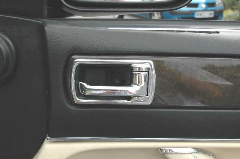
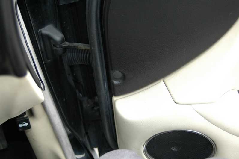
10.2.1 - Loose Wing Mirrors ( ,
)
Gently prise off the plastic cover on the bottom of the hinge and use a long Philips head screwdriver to tighten the three screws. If the problem reoccurs, try Loctite or something similar to hold the screws tight, or alternatively fit a slightly fatter screw.
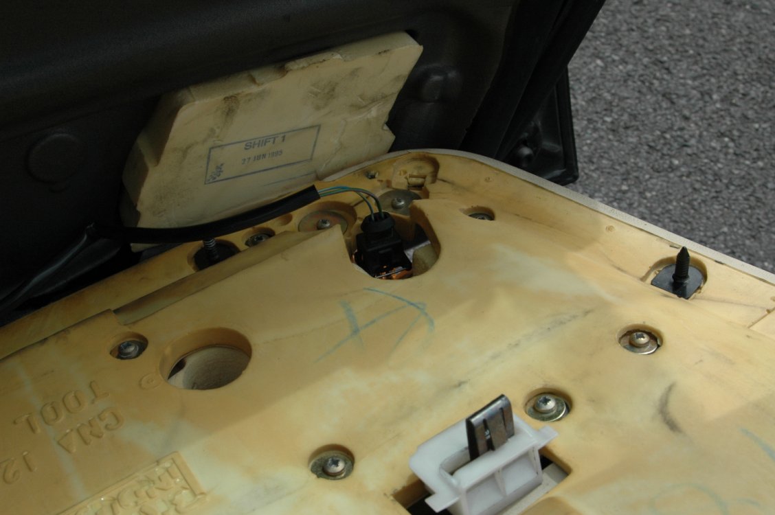
10.2.2 - Changing the electronic window/mirror control ( Olly,
June 11, 2005
)
Starting out is relatively simple...using the flatheaded screwdriver, remove the plate behind the door opener.
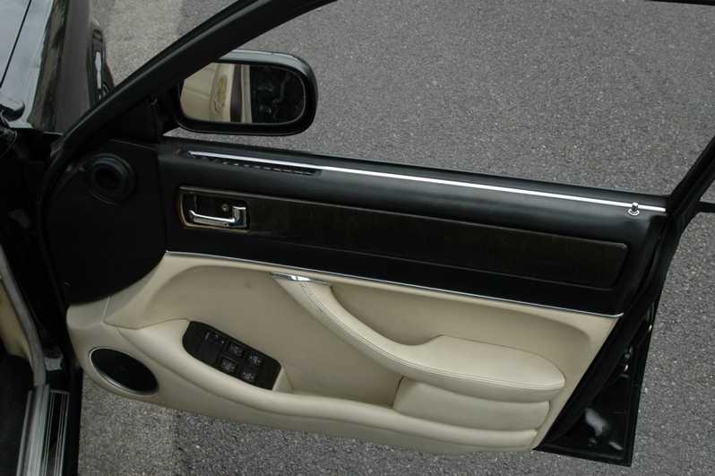
Remove the screw there, and the plastic behind of the doorhandle should come out with relative ease!
Press on the wooden panel and slide it towards the steering wheel, it should then leaver out without too much fuss.

With the wooden panel off, there should be two screws behind that (sorry, no picture!), remove these and the top half of the door should become loose. Pull this up at the lock end (and make sure the m

With the top half of the door pulled back, you should be able to get at the top screw that holds the door panel on.
Next, remove the red light cover at the bottom of the door (pulls downward), and remove the small flat-headed screw (note, may be a philips!)
The door assembly should be fairly loose by now, the final part is to remove the black lug found on the inside of the door near the hinges. With that removed, gently pull the leather assembly backward
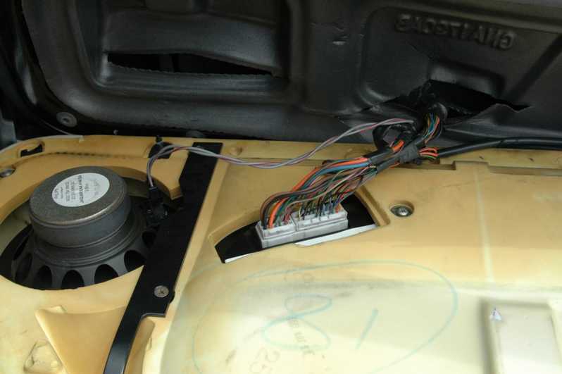
The door assembly should be fairly loose by now, the final part is to remove the black lug found on the inside of the door near the hinges.
Finally, you should have the door assembly clear now.
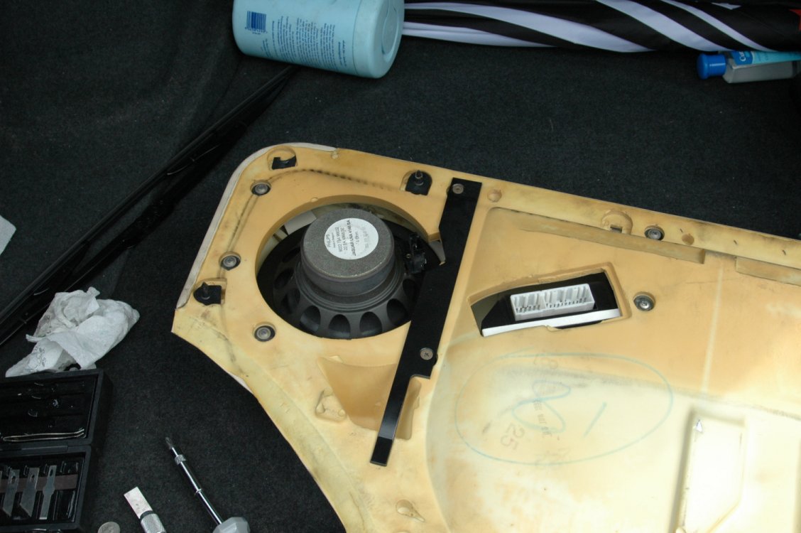
Flip it over & remove the bar on the back (note, make sure you put this back on during re-assembly, or else you ll have to go through all the above again :)
|
If like mine, your electric window control unit has lost the little joystick that lets you adjust the mirrors, changing it is actually a lot simpler than it looks. Tools needed are a flatheaded screwdriver, a decent sized phillips screwdriver and a pair of pliers (although, this could probably be swapped for a ratchet bit of the appropriate size - will check & find out what size it needs to be!).
I picked my replacement unit up from JoJags for a very reasonable Ł60+vat (worked out at about Ł75 after vat & postage), they were great...I ordered it on Thursday, and it was here on Friday morning!
I'd also recommend picking up a couple of spare clips which hold the leather half of the door onto the frame, as two of mine were broken in the process (will add the Jaguar part# when I get round to picking a couple up!)
One final note, I'm not a mechanic/professional at this, although this is really as far as I'd want to go with fiddling with my Jag...if at any point, you're not happy or something doesn't seem right, stop & get someone who is a professional...it'll be a lot cheaper than the alternative :)
10.4 - Keys ( ,
)
Like the XJ40, the X300 uses Tibbe style keys. If the master key is lost, these can be cut from a code which can be derived from an existing key.
The lock has 8 tumbers, and for each tumbler the key has either no cut ( code 1 ) , a half cut ( code 2 ) or a full depth cut ( code 3 ). The eight digit code is simply a digit per tumbler, reading from the body of the key towards the tip.
10.5 - Rear Fuse Box Access and Seat Removal ( ,
)
Set in the rear floor carpet, just ahead of the seat leather, are two screws which allow the vertical panels at the front of the seat base to be removed. This gives access to the left and right rear fuse boxes and relays.
There are then two more screws holding the rear seat cushion. Push the seat belt buckles down through the hole they come out of, before then lifting the cushion.
The seat back is held in place by two screws in the middle and two at the edges, visible where the cushion used to be. To remove the back, first lift upwards and then pull out.
10.6 - Access to Boot / Trunk ( ,
)
If the locking mechanism fails or no power is available, it is possible to open the boot using a long thin screwdriver through the lower right licence plate mounting hole.
Follow the linkage rod from the lock mechanism itself going left, towards the centre, to where it joins the catch mechanism and push here. It can help to shine a light through the left side licence plate hole, and also to get a second screwdriver in here to take a little of the tension off the catch itself, though not too much or it will spring back into place.
10.9 - Body Rust ( ,
)
Some vehicles have shown evidence of rust around the windscreen seals, on the A-pillar and around the sunroof. Whilst not serious, quick treatment will help avoid later problems.
11 - Electrical ( ,
)
11.1 - Fuses and Relays ( ,
)
Fuses are contained in 5 main fuse boxes as listed below. The descriptions are from the Jaguar handbook and aren’t always the clearest. When diagnosing a problem, bear in mind that several fuses may be involve in getting a particular component to function ( eg power feed, control relay feed, electronic control module feed ), so do check the full list.
Engine Bay Left |
|
|
F1 |
25 |
Heated Front Screen
– Right Side |
F2 |
10 |
Main beam headlamp
– Left side |
F3 |
25 |
Starter Solenoid |
F4 |
10 |
Dip beam headlamp
– Left side |
F5 |
10 |
Side light, indicator
and repeater – Left side |
F6 |
20 |
Windscreen wiper |
F7 |
|
Unused |
F8 |
15 |
Air conditioning
water pump |
F9 |
|
Unused |
F10 |
10 |
Horn 1 |
F11 |
30 |
Engine Cooling fans
– series & parallel modes |
F12 |
|
Unused |
F13 |
|
Unused |
F14 |
10 |
Horn 2 |
F15 |
25 |
Heated Front Screen
– Left Side |
F16 |
|
Unused |
F17 |
30 |
Engine Cooling fans
– series mode |
F18 |
10 |
Front Fog lamp –
Left side |
|
|
|
Engine Bay Right |
|
|
F1 |
|
Unused |
F2 |
10 |
Main beam headlamp
– Right side |
F3 |
|
Unused |
F4 |
10 |
Dip beam headlamp
– Right side |
F5 |
10 |
Side light, indicator
and repeater – Right side |
F6 |
5 |
Engine ECU |
F7 |
25 |
Air pump ( 6 cyl
) Ignition coils ( 12 cyl ) |
F8 |
10 |
Air con clutch (
note separate inline fuse ) |
F9 |
|
Unused |
F10 |
5 |
Alternator, Lighting
control module – Right side, Air con clutch, windscreen &
headlamp wash heaters |
F11 |
20 |
Engine ECU relay
supply, injectors |
F12 |
10 |
Engine ECU, Starter
Relay, ignition coil sensing and air pump ( 6 cyl ), injection
relay and ECU sensors ( 12 cyl ) |
F13 |
10 |
Windscreen washer
pump |
F14 |
10 |
Oxy sensor heaters,
idle speed control valve |
F15 |
|
Unused |
F16 |
10 |
Air pump control,
Vacuum valve ( 12 cyl ), intercooler water pump ( 6 cyl supercharged
) |
F17 |
30 |
Headlamp power wash
pup |
F18 |
10 |
Front fog lamp –
Right side |
|
|
|
Rear Seat Heelboard
– Left Side |
|
|
F1 |
|
Unused |
F2 |
10 |
Heated Door Mirrors,
Instrument Illumination |
F3 |
15 |
Seat motors –
Right side |
F4 |
15 |
Seat motors –
Right side |
F5 |
10 |
Instruments |
F6 |
5 |
Seat ECM, low power
door switches, mirror motors |
F7 |
30 |
ABS pump |
F8 |
|
Unused |
F9 |
20 |
Cigar lighters |
F10 |
5 |
Cruise control |
F11 |
20 |
Heater blower –
left side |
F12 |
5 |
Instruments |
F13 |
15 |
Steering Column
motors |
F14 |
10 |
Auto transmission
ignition switched supply |
F15 |
30 |
Window motors –
left side |
F16 |
5 |
ABS ignition switched
supply |
F17 |
|
Unused |
F18 |
10 |
Air Con supply |
|
|
|
Rear Seat Heelboard
– Right Side |
|
|
F1 |
15 |
Central Locking |
F2 |
5 |
Gearshift interlock,
Centre console switches, interior lighting switch |
F3 |
15 |
Seat motors –
left side |
F4 |
15 |
Seat motors –
left side |
F5 |
5 |
Auto transmission
ECU |
F6 |
|
Unused |
F7 |
30 |
ABS Control |
F8 |
10 |
Interior lights,
boot lights |
F9 |
25 |
Seat heaters |
F10 |
5 |
Diagnostic system,
Fuel pump relay coil |
F11 |
20 |
Heater blower –
Right side |
F12 |
10 |
Air con, Seat ECM,
Mirror heater relay, Power steering |
F13 |
|
Unused |
F14 |
10 |
Mirrors, heater
rear window, cigar lighter, rear lighting control |
F15 |
30 |
Windows – Right
side |
F16 |
10 |
Windscreen wipers,
Front screen heater control, Front lighting control – left
side, water pump relay, headlamp levelling, clock |
F17 |
15 |
Airbag |
F18 |
15 |
Sunroof |
|
|
|
Battery Compartment |
|
|
F1 |
25 |
Stereo |
F2 |
5 |
Tail and plate lights
– left side |
F3 |
15 |
Reverse lights,
stop and indicator light – left side |
F4 |
10 |
Security system |
F5 |
10 |
Main CPU |
F6 |
5 |
Diagnostic system,
phone |
F7 |
30 |
Fuel pump |
F8 |
15 |
Boot release, aerial,
stereo unswitched feed |
F9 |
15 |
Rear fog lights,
stop and indicator light – right side |
F10 |
5 |
Stereo control relay |
F11 |
25 |
Towing module |
F12 |
5 |
Phone and accessory
relay |
F13 |
10 |
Accessories |
F14 |
|
Unused |
F15 |
25 |
Heated rear window |
F16 |
5 |
Airbag warning |
F17 |
|
Unused |
F18 |
5 |
Tail and plate light
– right side |
|
|
|
11.10 - Sound System ( ,
)
11.10.1 - Radio Wiring ( ,
)
The purple/orange wire in the radio wiring harness will mute the radio when grounded. It can be directly connected to the yellow wire of a Nokia car kit for automatic mute when the phone is in use.
11.10.2 - Radio Aerial/Antenna Replacement ( ,
)
These seem to be a commonly failing item. The wiring connector was changed during the lifetime of the car, so ensure you get the right one when replacing.
When replacing, lift it slightly up at the bottom and then slide it down over the window button.
11.10.3 - Radio Aerial/Antenna Maintenance ( ,
)
Periodically wipe the raised antenna with a damp cloth in an upward direction, which avoids pushing dirt into the mechanism. Switch-cleaner is preferable to WD40 as a cleaning agent, as it does not leave a sticky residue behind.
The standard radio unit will periodically display a message requesting that the aerial mast or cassette unit be cleaned. This is a useful reminder, but more frequent cleaning, particularly in dirty road and weather conditions, may be advisable.
11.10.4 - Radio Connections, CD Player and Cartridge Removal ( ,
)
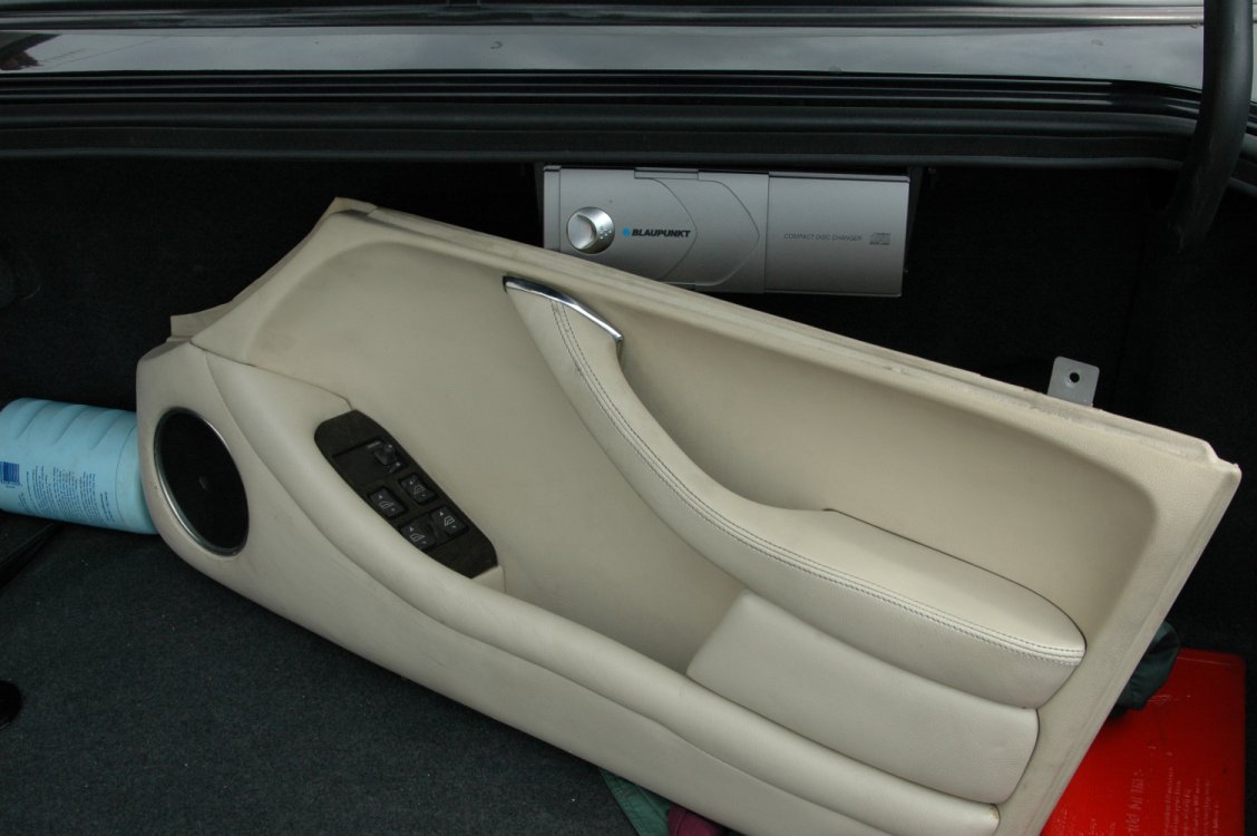
The standard radio has an 8 pin DIN style socket for attaching the CD stacker, which is wired through into the boot. Where no factory CD player is fitted, the Alpine CHM620 can be fitted using the existing wiring and will be controlled from the standard head unit.
The stereo also has a 5 pin DIN socket for connecting a separate power amplifier, available in some markets to drive a sub-woofer.
In addition, there is the main 20 pin connector to the stereo, with pins 1 - 10 on top going right to left and pins 11 - 20 on the bottom. 1 and 10 are 12V feeds, 4 switches the lighting on and off and 3 is a variable feed from the lighting dimmer circuit.
If the CD cartridge appears to be stuck, try pushing a credit card or similar under the cartridge to the right of the eject button.
11.11 - LCD Clock ( ,
)
Clock modules occasionally suffer from faint displays, caused by bad contacts between a circuit board and flexible ribbon cable inside the unit. It is possible to make a repair, though some may consider it to be a less than professional fix!
Access can be gained following the instructions in section 10.1. Remove the connector at the rear of the clock unit itself, undo the four screws attaching it to the rest of the assembly and then take it to a bench area for further work.
The unit itself is opened by undoing the small screws at the rear and releasing the plastic tabs. Whilst the unit is open, take care not to lose any of the small components in there. Release the LCD panel itself by carefully spreading the black tabs holding it into the white plastic bracket. The panel is attached to the main circuit board by a ribbon cable, and it is the connection at the circuit board end that is the problem.
Tape the ribbon cable in place and use a business card or piece of pizza box ( both have been successfully deployed! ) to put pressure on the ribbon cable where it connects to the pcb, behind the white plastic bracket.
Take the unit to the car in plug it in. Use the time set buttons to cycle through all the digits to make sure the fix is complete before reassembly. If segments are still missing or faint, additional pressure may be needed on the ribbon cable.
When all is working, reassemble the clock unit and then refit into the centre console. Attach the cable and take care not to stress any other wires as you fit the console back into position.
11.12 - Memory Seats and Steering Wheel ( ,
)
Some models are fitted with the memory seat, steering wheel and mirrors functionality. The ECU's associate the position of the various devices with a particular key fob and adjust them accordingly.
The motors, particularly for the steering wheel, are known to fail and replacement has been the only solution reported. In some cases, the system appears to become inactive, which can be overcome by disconnecting the battery for an hour or so.
11.13 - External Temperature Sensors ( ,
)
These are located in the brake cooling ducts, behind the front bumper and in front of the wheelarch liner. Access can be obtained by removing the front undertray.
The left hand sensor is used as input to the climate control system. The right hand sensor is used to control the washer reservoir heater and washer jet heaters, active below 4C, and to control the heated seats, active below 26C.
11.14 - High Level Brakelight ( ,
)
Where fitted, this is driven from the relay located in the red, right hand socket in the boot fuse box. The relay is identical to the two others adjacent.
11.15 - Front Indicator Bulb Replacement ( ,
)
The manual indicates a special tool is required to remove the indicator unit from the front bumper. The tool is flat plastic blade, and can therefore be improvised yourself. You can use metal if you are careful to protect the finish on the bumper.
The blade slots into a gap on the inboard side of the indicator unit and releases an internal catch by pushing it to the outboard side of the car.
Bulb replacement and refitting the unit and then straightforward.
11.16 - Sports / Normal Switch Light Replacement ( ,
)
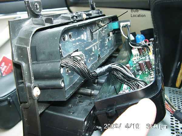
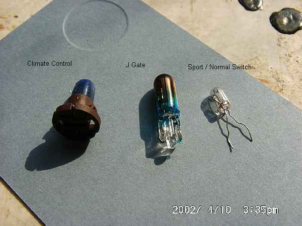
|
Jaguar does not offer a replacement bulb, but insists you replace the switch. However, replacement is straightforward with a sub-miniature bulb as sold in electronics shops.
To gain access to the switch, remove the ashtray and plastic transmission selector surround (see section 10.1 of this guide).
Using a small screwdriver, release the clear plastic lugs holding the lower part of the switch into the black upper casing and remove the lower part of the switch. The bulb sits inside a small piece of rubber which itself sits on two metal prongs which carry the current to the bulb. The wires from the bulb go back up through the rubber in the same holes as the mounting prongs.
Remove the blue cap from the bulb then pull the rubber mount off the prongs. Gently pull the bulb wires through to the lower side of the rubber, straighten them, then lift the bulb out of the rubber from the top.
To refit, put the new bulb in, making sure the wires go through the two tiny holes in the rubber mount underneath the bulb. Bend the wire round and up inside the mounting holes, then push the rubber back down onto the prongs. Make sure the switch position is the same on upper and lower halves of the switch, then click the lower assembly into the upper casing.
Reattached the wiring and refit the plastic transmission surround and ashtray.
11.2 - Headlight Removal ( ,
)
The headlights are mounted on three ball joints and can be removed by pulling the whole unit firmly. They are sealed beam units and must therefore be replaced as an entire unit should the glass be broken
11.3 - Climate Control Test and Diagnosis ( ,
)
The climate control system is significantly different from earlier XJ40 models in that all flaps and valves are electrically operated, with no reliance on engine vacuum. The system is of the 'constant air flow' type, meaning that fan speed is adjusted based on road speed to maintain the desired flow rate.
The system can be put through a self-test procedure as follows:
Warm the engine then switch off. Press both 'Auto' and 'Recirc' buttons and hold whilst restarting the engine.
All the panel LED's and LCD display will flash. Any areas failing to flash suggest a problem with the bulb, display or function in that area.
Press 'Auto'. If the display is zero, then no error codes are stored. Any other number is an error code. Use 'demist' to cycle through up to five stored codes. Press 'demist' and 'heated rear window' to clear a displayed code. Code 23 indicates low refrigerant pressure.
Press 'Recirc' to enter diagnostic mode. Repeatedly pressing 'Face' will step through the 8 different combinations of vent actuation and you will be able to hear and feel vents and fan operating.
Pressing 'Off' will restore the unit to normal operation with the default settings.
List of control codes:
0 - Normal Operation - No fault codes present, wait 30 seconds for system
self-check.
11 - Motorized In-car Aspirator (sensor element)Open / short circuit. Panel
fault codes are not stored for blown aspirator failure of motor.
12 - Ambient Temperature SensorOpen / short circuits.
13 - Evaporator Temperature SensorOpen / short circuits.
14 - Engine Coolant Temperature InputInstrument pack output.
15 - Heater Matrix Temperature SensorOpen / short circuits.
21 - Solar SensorOpen / short circuits.
22 - Compressor Lock SignalOpen / short circuits. Low gas charge, low
compressor oil, loose belt.
23 - Refrigerant Pressure SwitchOpen / short circuits. Low gas charge*.
24 - Differential PotentiometerOpen / short circuits.
31 - LH Fresh / Recirc. PotentiometerOpen / short circuit in pot.
feed. In certain circumstances, the motor can over-travel and log further
faults. Cycling the ignition two or three times can cure this.
32 - RH Fresh / Recirc. Potentiometer
33 - Cool Air Bypass Potentiometer
34 - Defrost Potentiometer
35 - Centre Vent Potentiometer
36 - Foot Potentiometer
41 - LH Fresh / Recirc. MotorCheck for short / open circuits in motor drive
lines. Motor flap sticking / jammed.
42 - RH Fresh / Recirc. Motor
43 - Cool Air Bypass Motor
44 - Defrost Motor
45 - Centre Vent Motor
46 - Foot Motor
Other symptoms that don't generate codes
No heat - Airlock in system. Water pump inoperative. Water valve stuck
closed. Faulty engine coolant thermostat.
One vent failing to open or close - Broken linkage.
Poor airflow - Blower motors - incorrect operation (eg fuses blown).
11.5 - Windscreen Washer Pump and Jets ( ,
)
The pump is located on the side of the washer fluid reservoir, in the wheel arch on the right side of the car.
To access, remove the wheel and pull out the clips at the front and upper sides of the plastic wheel arch cover. You can now pull the cover aside sufficiently to access the pump.
Unplug the pump and pull it from the tank, noting that any washer fluid will pour out.
A stuck pump can sometimes be repaired by removing the sealed top, lubricating the internals and then resealing using glue and/or melting the plastics together.
The jets are held in place with a central screw. Loosen the screw to allow the sprayer to be lifted upwards and the water and electrical connections removed.
11.6 - Remote Key Fob Programming ( ,
)
Open the boot lid and drivers door, and switch on the ignition. Rock the valet switch, in the centre console, 5 times. The system will chirp to indicate it has entered learning mode.
On models with seat/mirror/steering wheel memory functions, the first remote will be linked to memory 1, second to memory 2 etc.
Press the larger, lock, button of the remote. The system will chirp to confirm it has got the signal. If it doesn't receive any signals for 15 seconds, it will chirp twice and exit learn mode.
To programme further remotes, rock the valet switch once. The system will chirp twice for remote number two, three times for number three etc, then press the lock button of the remote as above.
When finish, wait 15 seconds for the system to time out and chirp twice, turn off the ignition, close the doors and boot lid and the job is done!
11.7 - Dim-Dip Mirror ( ,
)
These seem to be a commonly failing item. The wiring connector was changed during the lifetime of the car, so ensure you get the right one when replacing.
When replacing, lift it slightly up at the bottom and then slide it down over the window button.
12 - Common Problems & Fixes ( ,
)
This section simply lists the common problems reported
by members of the list, together with references to the fixes. The list
is in no particular order.
Sticking Thermostat |
Slow warm up |
5 years |
Replace – see
3.1 |
Failed Coolant Hoses |
Coolant loss |
5 years |
Replace – see
3.4 |
Supercharger Idler
Pulley |
Reduced power |
80 – 100K miles |
Replace – see
2.6 |
Memory seats and Steering
Adjustment |
Failure to adjust |
3 years |
Reset or Replace –
see 11.12 |
Dim-Dip Mirror |
Failure to dip |
3 years |
Replace – see
11.10 |
Wheel Alignment |
Worn front tyres,
tramlining or vague steering |
After kerbing or high
street tyre shop adjustment |
Adjust – see
9.3 |
Sticking throttle |
Increased idle speed |
Often follows cold
running |
Clean, may replace
spring – see 4.3 & 4.4 |
Failed EGR Valve |
Check Engine |
|
Replace – see
6.8 |
Fuel Gauge Sender |
Inaccurate fuel gauge
when full |
Early models |
Repair or replace
– see 4.2 |
Cracked Exhaust Manifold |
Visible cracks, noise |
4 years |
Repair or replace
– see 2.5 |
LCD Clock |
Faint display |
4 years, early models |
Replace – see
11.11 |
Dirty throttle body
or bad plugs |
Uneven idle |
Often follows cold
running |
Clean – see 4.3
Check – see 5.1
|
Loose Mirrors |
Loose mirrors |
5 years |
Tighten – see
10.2 |
Rust |
Rust |
5 years |
Remove and repaint
– see 10.3 |
|


