|
1 - Index ( ,
)
10 - Steering ( Chris Burdo,
June 7, 2005
)
10.1 - PAS top cover shaft seal fix,(Speedy-Sleeve) ( Craig Kercheval,
September 23, 2003
)
Unlike many of the initial postings, this one is not to pose a
problem, but to post a solution. It involves the installation of a repair
sleeve (called a "Speedy Sleeve) onto the top shaft of the power steering box.
Hopefully, this info will come in handy for some of you.
Several months ago, I noticed a fairly major leak from the Power
Assisted Steering box. I saw that fluid was not only leaking with the car
running, but even when the car was resting in my garage. The leak was
coming from the seal around the shaft which connects to the steering column.
This was puzzling, since I had recently replaced the seal - on two
separate occasions to try and stop the leak. Since I had followed Jaguar's
instructions carefully when disassembling the top cover of the box and since
I renewed not only the seal, but the two o'rings which are part of that
component, I was surprised (and dismayed) that the leak continued as it had
before I essentially rebuilt the top cover those two previous times.
During the course of my research to find a solution I got
several doses of good advice, not to mention moral support
from Chris Burdo, one of the listers here. Now that I have
finally found the right fix for this leak, Chris suggested that
I post my findings to this group. So, while the solution here is
unsolicited at this time, perhaps it will come in handy for anyone's
Jaguar sedan who experiences leaking from the same spot as on my
car.
I'll try to summarize here, based on the learning curve I just
went through.
Car:
1966 Jaguar 3.8S with 40,700 total miles.
Problem:
Leaky Power Assisted Steering box from the top shaft seal. This
is the shaft which connects to the steering column. After years of
trouble-free operation, fluid began leaking from the seal when the
car was running, and continued to leak when the car was not running.
Continued leaking approx. 1-2 oz. a day with the car sitting in the garage.
Solution:
Installed a "Speedy Sleeve" on the top shaft. Replaced the shaft
seal and the two o-rings in the top cover.
Reference:
Jaguar 3.4S and 3.8S Models Service Manual. See page I-38
section on "The Top Cover" plus illustrations.
Replacement Parts:
Speedy Sleeve - Part # 99076 made by Chicago Rawhide
Seal (double-lipped) - Part # 7443 made by Chicago Rawhide
O'ring - Size .028
O'ring - Size .042
Procedure Notes:
Rather than repeat text from the Jaguar Manual, I have only
commented based on my recent experience with this procedure.
(The assumption is that the box has been removed from the car
for this procedure)
Speedy Sleeve comes with clear instructions and a tool included
to drive the sleeve onto the shaft. Basically, installation involves driving
the sleeve onto the shaft to cover the area of the shaft which is directly
inside the top cover seal. On my car, I stopped driving the sleeve at a
point where about 1/4" of the shaft shows beyond the splines. Although the
Speedy Sleeve was the correct diameter for the shaft, the splined part of the
PAS shaft on my car needed to be sanded down in order to allow the sleeve to
go over the splines without binding. I used 400 grit paper on the splines,
checking until only slight resistance could be felt with the sleeve
slipped over the splined part of the shaft.
I removed everything from the top cover, per the Jaguar Manual
instructions, except the shaft seal, which I left in place for measuring
purposes. Before removing the old seal from the PAS top cover, measure the
distance along the shaft where the sleeve must be installed. The sleeve is only
about 1/2" long, so it is critical that it be driven directly under where
the seal will sit with the top cover in place.
Use a non-hardening sealant, like Permatex, which will act as a
lubricant, when spread thinly on the inside of the sleeve before driving it
along the shaft.
After gently driving the sleeve in place over the shaft, and a
final check of the top cover with the old seal in place, the old seal can be
removed from the top cover. The new seal can then be pressed, or lightly
drifted in place inside the top cover. I used a thin coat of Permatex
non-hardening sealant around the outside and front of the seal, careful not to
get any on the rubber seal. After the seal is in place, of course, it must
be lubricated with the same fluid used in the PAS.
With the new o-rings (lubricated with same fluid used in the
PAS) installed and all components back in place in the top cover,
the top cover can then be tightened down onto the steering box.
10.2 - S-type Steering box rebuild ( Chris Burdo,
January 27, 1998
)
Yes your power steering box can be rebuilt, will it work when
you put it back together, how lucky do you feel? All kidding
aside,it can be done. I have just recently put mine back together
after renewing all the seals and gaskets. I ordered a rebuild kit
from Welch Jaguar in Ohio, USA for about $45.00. Make sure when
you order your kit that you know which box you have ( the first
or second type), also whether or not your box is steel or aluminum,
this determines which kit fits your box. ( I didn't realize
this and told them I had the second type box and still received
the wrong kit). The quick way to make sure that the kit is the
right one is to make sure that the output shaft seal that you
receive is the same one as the one you remove from your box.
(The first box uses a different size seal).
In order to rebuild the steering box you will need alot of
patience and maybe a few Guiness stouts wouldn't hurt too! The
thing you have to remember is that on either end of the worm gear
there are ball bearings and roller bearings,(This is shown pretty
clearly in the manual), so care must be taken in removing the
covers off of the ends. Take the manuals advice and put a large
pan or cookie sheet under the box during the dis-assembly and
assembly stages,( I did this and went one step further and put
a quart of oil in the pan because it took about two seconds for
me to realize that bearings bounce!, nothing like learning by
experience!).
Once you have all the covers off and you are about to remove
the worm assembly be careful to make sure that the nut doesn't
spin around on you as it is weighted to spin towards the right.
should it spin around on you, you will have the ball bearings
fall out from the inside of the assembly. Now you don't say
whether or not your power steering works but just leaks or if
it does not work and leaks. If it works but leaks I don't think
that you have to take apart your worm assembly, (I only say this
because there are 37 ball bearings that surround this worm gear
and I think you only need to take this apart if you happen to
to be in my position where I have no steering assistance.
If you already have some steering assistance I think just cleaning
it up will do, just make sure that you put a clamp on either side of
the nut to make sure that the nut does not spin. The only problems
I encountered during the rebuild is (a) That the rebuild kit comes with
alot of O-rings, you won't need them all but I took careful care to
make sure that I had replaced them all,(you will have some left though).
(B) putting the worm assembly back in was an effort. The manual states
to use a piston ring clamp, well I went out and bought one for up to
6" and I had to alter this tool and cut up alot the sleeve metal
to finally get the worm nut back in to box. The problem is that
unlike a piston in your block this has two rings back to back,
the rings themselves must have the splits in them 180 degrees
apart. To make thing more interesting Jaguar made sure there is
also a lip (for the end cover), that you must get past with the
rings compressed. This took alittle time and I invented some new
words for the english language. Other than this the rebuild was
pretty straight foward. One other item, make sure that you mark
your lower steering shaft settings as they are before removal
of the shaft and box. I found that "white-out" (typing correct)
works pretty good and its pretty durable. Make sure you mark it
on the shaft, the firewall, the box shaft that the lower shaft
is hooked to, the more places that you have it marked than the
easier it is to install!
Chris Burdo added on July 7th, 2002:
Quick word regarding seals for the PAS pump, or any other part that
requires a seal for that fact. Look in your phone book for the nearest
pump repair shop in your area and go there when you are going to rebuild
your steering box or PAS unit. Take to them exactly what you took out of
the unit, (or bring the unit..nothing that I've never done before, that's
for sure), and they will match it up and give you just what you need to make
it proper again. (Oh, it will still probably leak mind you...I'm still
convinced that they leaked from new and that the engineers from Jaguar are
still laughing over it.). I've bought enough seals and O-rings at the
moment to probably do 3 steering boxes for a cost of $20.00. On a related
matter you should be careful on purchasing O-rings. Pump rebuild shops will
give you proper ones that are made to handle oils and whatnot whereas if you
purchase them from a plumbing section at your local hardware store you may
find out the hard way that they aren't suited for your application.
10.3 - Replacing Steering Column Bushings ( Bob McAnelly,
February 22, 2006
)
Replacing the bushes is one of the easier repair tasks on your
car, and very drastic performance improvement once you are done
pretty instant gratification. But, just like any other old car
repair, what looks like an hour job ends up taking four times
as long, plus a wasted week while you wait for the "other" part
you broke to come in the mail, etc.
But, the process is rather simple. While it might not be
absolutely necessary to remove the steering wheel, it is a lot
easier if you do. Remove the 4 screws from the back of the horn
push assembly, then the three screws holding on the horn ring.
The jam nut and main nut holding on the steering wheel come off next,
and out with the wheel. Don't lose the two half moon spacers.
At the bottom of the column, loosen the hose clamp that holds
the column to the bulkhead. While down there, disconnect the purple
horn wire from the column. Remove the trim panel below the instruments,
and note how the clock and odometer cables poke through.
If an auto trans. car, disconnect the shift linkage. Open the bonnet and
remove the bolt from the lower end of the column center shaft where it
attaches to the u-joint. You need to remove the nut and push the bolt
out of the end of the shaft, as it is an interference fit. Go back
into the car and remove the two screws attaching the turn switch, then
the two bolts that attached the column to the instrument panel, and
note the location of the alum. spacers. The column should now
come out. As the central shaft might not want to come out of the u-joint,
give it a good tug. You might need someone under the bonnet to help you get it out.
Once removed, there is a plastic or bronze "fork" that keeps the central shaft
inside the column. It is hidden under an aluminum collar down near the
bottom of the outer column. Pry the collar off, and the fork can then be removed.
Pull out the column and you will then gain access to the two bushes.
Remove the old ones (or the partial remains of the old ones) and stick in the new ones.
I have found the new bushes to be slightly over-sized- with the hole in the center a bit
too small. I have used a file or sandpaper to open it up a little. You don't want them
too tight, as you will have difficulty in turning the steering wheel, or the wheel will squeek.
I hone them out and add a little white grease.
And, of course, it all goes back the reverse of how you took it apart. Hardest part is
getting the end of the steering column back into the universal joint. It helps if you have
someone up front to guide the end of the shaft into the joint. It can only go one way,
as there is a flat spot on the shaft over which the bolt passes. If you don't get it
into the correct spline alignment, you will not be able to slip the bolt back in.
You don't need to force the bolt-- if it won't go in, you do not have it indexed properly.
Might help to mark the two ends before disassembly with paint or a scrape of the
metal pieces so that a shiny scratch is created.
While you have it all apart, clean the horn contacts inside the column and maybe
bend the contact finger to ensure that it makes good contact. When slipping the
central shaft back into the column, make sure you do not bend the contact. You
should be able to ease it past the contacts through the hole in the column where the
horn wire is attached. It will be quite obvious once you get it all apart.
Several of the parts sellers list a kit for rebuilding the horn contacts. The ones I have
seen to date are junk. The contact pieces are soft brass and not spring bronze, and
they do not keep their shape. You are much better off keeping the original pieces.
However, if your parts are damaged beyond repair, before ordering one of those repair kits,
ask on this list if anyone has found a reliable supplier.
11 - Front Suspension ( Chris Burdo,
June 7, 2005
)
11.1 - DIY Front Coil Spring Compressor ( Paul Saltwick,
March 13, 2003
)
From Paul Saltwick, March 13th, 2003:
The safest way to remove the springs is to use 4, 3/8-24
threaded rods 12 inches long. Remove the shock, put a floor
jack under the spring pan, remove one of the corner spring
pan bolts and replace with a threaded rod, 3-4 washers and a nut.
The idea is to put a threaded rod at the four corners of
the pan and remove all the bolt and slowly lower the pan by
backing off the nuts evenly. It is a slow procedure, but
it helps to use a few washers to raise the nuts proud of the pan
lip and use ratcheting box wrenches. I will admit to using 2 or 3
rods when in a hurry, but it is tricky to get the pan to lower evenly
because it is not vertical. The force involved is considerable and I
was not comfortable with the one central rod idea, because I did not
have a suitably hardened threaded rod.
11.1.1 - Coil Spring Replacement ( Dan Davis,
September 21, 2005
)
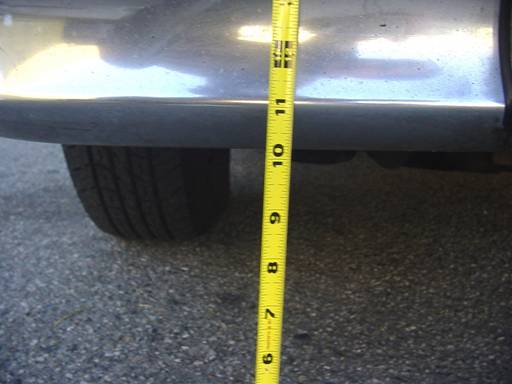
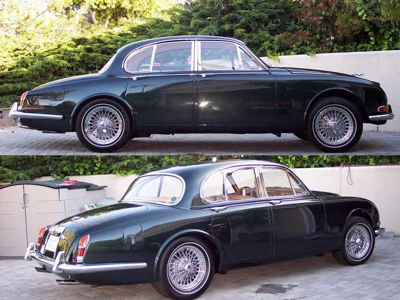
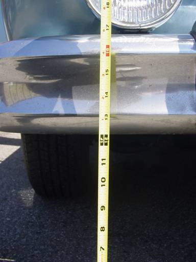
Original ride height
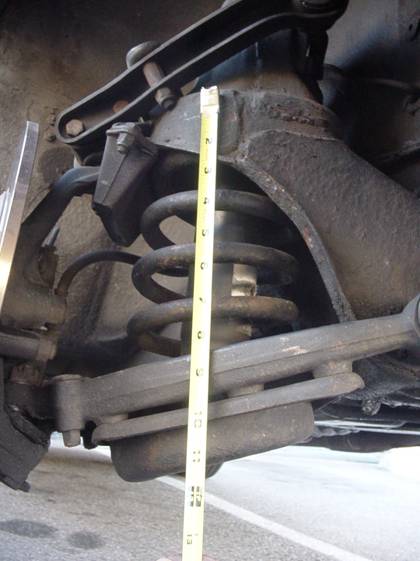
Measuring the starting length of the spring
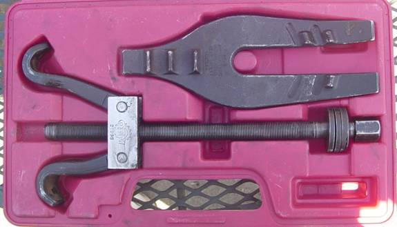
Spring Compressor rented from AutoZone
Spring Compressor installed, bottom view
Spring Compressor installed, side view

Spring Compressor installed, spring removed
Original packing piece for the spring
New and old spring side by side.
Finished ride height. Two inches higher after installing the new springs!
|
Changing the Coil springs in a Jaguar Saloon
By Dan Davis 1959 3.4 Litre RHD Automatic
Legal Disclaimer:
The Haynes manual starts the section on removal and refitting of coil springs as follows:
“WARNING: These are extremely heavy springs of about 14” free length. We strongly recommend that you do not attempt remove them unless you are fully competent to do so and have all the necessary equipment. Any attempt to remove, or replace, these springs using unsuitable equipment could result in a serious accident.”
Now that’s an understatement if I ever heard one. The information which follows is my own account of how I managed to survive the procedure. You may not be as fortunate.
When I purchased my car, it was fairly evident that it sat to low in the rear. So, one of the first things that I had done, was to pick up a set of replacement leaf springs and have my mechanic replace them.
Before I sent it off for the repair, I crawled underneath to get a look, and found that there were cracked leaves on both sides. This obviously needed to get done!
When I got the car back, I was very disappointed to see that the front of the car now seemed to droop. And to make matters worse, the new leaf springs creaked like the dickens.
This turned out to be just one of the repairs that my mechanic charged me 50% more than the quote for, and I ended up redoing myself at a later date. But that's a separate story.
The coil springs scared my a little. Years ago I had a Ford Capri, and due to financial circumstances, was forced to replace the McPherson struts myself.
The struts were surrounded by coil springs which had to be compressed before I could remove them from the car.
Not having the right tools for the job was always my specialty, so I improvised. I grabbed a bunch of coat hangers, cut about 40 four inch pieces, and began the process of wrapping them around a pair of coils at a time, cinching them together by twisting the loose ends with a pair of vise grips. It was tedious and slow, but eventually, I got the springs down to a point where they could be removed, and carefully set to the side while I removed the struts.
It was shortly thereafter, that my roommate came home with the groceries. With the bags in her arms, she could see that I was under the car, but didn't notice the coil springs sitting against the side of the house. Naturally, she kicked them. I didn't see it myself, but a neighbor later told me that the springs reached an altitude of about a hundred feet, and just missed taking my roommates head off by inches!
The coil springs in a Jaguar saloon are much stronger than the coils in a Capri, and it was with this in mind that I spent a year or so reading up on the procedure, and browsing through the archives to see how others had tackled the problem.
I advise this process over all others. The manual is poorly written, your mechanic does not know what he's talking about, but the experience of others on this list is invaluable when determining the correct and incorrect way to go about things.
In general, most every listing was in agreement. The proper Churchill tool is worth more than the car, and can not be found.
Some had tried garden variety spring compressors and found that they fouled inside the shock tower, and made the job difficult if not impossible. The general consensus of opinion was to locate several lengths of 3/8" x 24 grade 5 threaded rod stock, cut these into either three or four lengths of 10" - 12" and carefully remove a bolt from the spring plate and replace it with the threaded rod backed up by a couple of washers and double nuts for safety. The group which called for three rods, also preferred adding a single 5/8" rod through the center of the spring to carry the bulk of the load. Others seemed to feel that four of the 3/8" were sufficient, although warnings were given in both cases. Either way, this procedure meant backing off on the nuts in turn, to relieve the pressure on the spring plate, until the springs were loose and the spring plate could be removed. This sounded good to me, so I crawled back under my car to try and visualize the process before I gathered up the materials. What I found was not good news. The bolts which hold the spring plate to the lower wishbone sit in a 1/2" recess inside the spring plate. I tried to put an open end spanner on one of them, and found that I could only turn the bolt about a flat at a time due to the recess. I pictured myself under the car for a few days at this point, carefully backing the nuts down the rods a flat a time. It was time to go back to the archives. One post offered some hope, a lister had found a specialized ratchet tool at Sears which had a socket with a hole in it, allowing it to go over rod stock. This was just the ticket! Off to Sears where I located the unusual ratchet. But it could only be purchased as part of a set at $50. I gave this some thought, and determined that I would probably never use this tool again, and I did not want to spend more on parts and tools than it would have cost me to hire a mechanic to do the job.
The next day, I mentioned my troubles to a co-worker. He told me that his son had recently rented a spring compressor from Auto Zone, and replaced the front springs in his pickup truck. I told him that Jaguars were a bit different than pickup trucks, and these tools would probably be more trouble than they were worth. But just to be thorough I went down to Auto Zone to see what they had. I asked the counter guy if they had a good single rod spring compressor, and he said they did, and disappeared into the back to get it. When he showed it to me, I could not think of a good reason why I shouldn't give it a try, since I could rent it indefinitely, and they would refund 100% of the rental cost when I returned it. With a plan "B" in place, it was time to get started.
Back under the car, I went through the process of visualizing each process. The spring compressor began to look better and better as it only needed to pull the spring down a few inches against the pan, and at that point the entire assembly could be removed.
Step 1 - Measure the before height
Both sides measured the same, 11 1/8" to the crease in the bumper.
Step 2 - Measure the starting length of the spring
I would need this measurement to determine how high I would need to get the front end in order to remove the spring from the bottom. With the wheel off the ground, the spring measured about 11". The new springs were just more than 14", so I would need to plan on being able to compress the new springs at least 3" to get them back in the tower. Notice in this picture, the differences in angle between the spring pan and the coil. Some wrestling will be needed down the line to get this all to go back together!
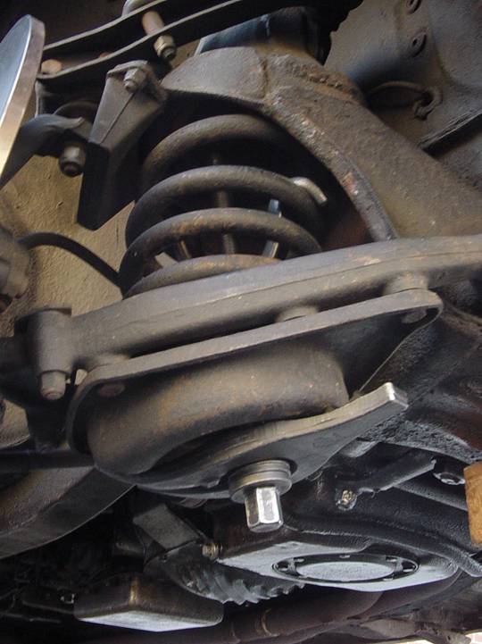
Step 3 - Get it up!
I blocked the rear wheels, and with a rolling jack in the center of the front cross member lifted both front wheels off the ground and supported the car with two jack stands for good measure. Pulled both front wheels, and removed the shock absorber from the left side.
Step 4 - Double check, and prepare
I measured the distance below the spring plate at 10", this I reasoned was enough to get the spring out. I then loosened each of the bolts a quarter turn and retightened to be sure I wouldn't be fighting with a seized bolt later in the process.
Step 5 - The big squeeze
Here is the coil compressor I rented. It is marked OEM 27035.
After applying some motor oil to the threads, I extended the claws to the end of the rod, and passed it up through the spring plate where I set the claws on the highest sections of coil that I felt didn't interfere with the tower. I then attached the forked plate over the bolt, below the spring pan, and adjusted its position so that I would have access to all 6 mounting bolts.
After 135 quarter turns of the ratchet wrench, the spring popped out of its seat at the top, and I knew it was loose.
Here, I sat back and gave it a good look. Somewhere in the distance I could hear a small voice saying "Tell me again how you lost your arm, Grandpa!"
This reminded me that I wanted to be real sure that I wasn't doing something very stupid before I removed the mounting bolts from the spring plate!
After I had convinced myself that it all made sense, I began removing the bolts, checking along the way for more tension than I would expect.
No worries! The spring, compressor and spring plate came out the bottom just as planned. Over on a table I set the assembly on it's side, and decompressed the spring to it’s full length, where I could remove the compressor and spring.
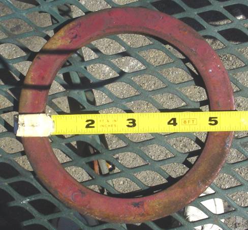
The other piece which fell out was the original packing piece that Jaguar introduced with the advent of the 3.4 Litre to give an extra bit of oomph to support the heavier engine.
As you can almost see from my award winning photograph, this piece is Ľ” thick, and measures somewhere around 5-3/8” in diameter.
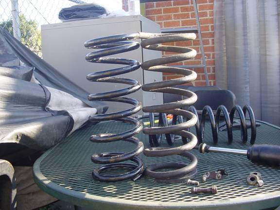
Now for the first moment of truth. I sat the old spring next to the new spring to try and determine how much more lift I could expect for my trouble.
Bugger! They are both virtually identical. If anything, the old spring is 1/16th taller than the new spring. This certainly puts a damper on my enthusiasm, but I resolve to carry on, just in case forces are at work which I do not understand :)
Step 6 – Installation is the reverse of this procedure.
The new spring sits in the spring pan with the flat side up.
The bottom of the spring is not flat, and the lower portion of the coil fits into the trough in the pan so that the end of the spring fits in the lowest part of the trough. I laid some pieces of duct tape into the trough before I fitted the spring in a foolhardy attempt to reduce spring noise down the road. I then taped the packing piece to the top of the spring so I would not have to worry about it falling off at an inopportune moment.
On goes the ratchet wrench, and 135 quarter turns later, the new spring is small enough to stuff back into the tower. You may recall earlier that I mentioned that the spring pan was not perpendicular to the tower. This is where that information comes in to play. In order to properly seat the spring and get the bolts in, I first screwed in the one bolt which could reach its threads. Then with a bottle jack, I raised the opposite corner in order that I could get the next bolt in place.
Now that all of the bolts and their respective holes are aligned, they were all tightened down, and the shock absorber was replaced.
This entire process took 2 hours. Broken down, that was 1 hour to do the actual work, and 1 hour spent contemplating my mortality.
The other side was completed 45 minutes later.
The second moment of truth
On go the wheels, down goes the jack, once around the block to settle the wheels and out comes the tape measure. As the many email message in my inbox will testify, you really can gain 2 inches in an afternoon!
Now that the car sits straight and level, I get to take a year off to investigate the replacement of my rear brake disks. Hopefully, AutoZone has a good hub puller!
11.2 - Front Subframe Removal ( Merritt Smith,
)
* REMOVE the splined bolt holding the lower steering column to the steering box. Failure to completely remove this bolt can result in damage to components in the steering column!
* If you have power steering, drain the system and disconnect the hoses from the steering box. Cover the hose ends and openings to prevent the entrance of contaminants.
* Jack up the front of the car high enough that the front tires can roll under the bumper. Support the car securely with heavy-duty jackstands.
* Remove the road wheels.
* Disconnect the front brake lines at the flexible hoses.
* Replace the road wheels.
* Support the suspension cross-member with a floor jack.
* Remove the bolts at the rear suspension mounts, sway-bar mounts, and remove the nuts and bolts at the front suspension mounts.
* Lower the suspension onto the wheels. Watch the steering column spline for binding. Roll the suspension out on the wheels.
11.3 - Lower ball joint replacement, XJ40 upgrade ( Ryan Border,
)
The lower balljoints in the small saloons consist of a well designed durable assembly. However, as the internal parts wear, they require occasional adjustment- usually achieved by reducing the shim thickness between the lower A-arm and the ball-joint cap- which accounts for wear. They also require periodic lubrication.
It is not uncommon to find the lower ball joints in need of replacement, due to neglect from a previous (or sometimes the present) owner. In these cases, it is possible to replace the lower ball-joint with a unitized assembly from an XJ40 (1988 and up XJ6 in the US). This assembly requires no adjustment or lubrication. However they are rumored to be less durable than the original units IF the original units are properly, and regularly, attended to. 60Kmi instead of 90Kmi according to one source. Many Jaguar owners gladly trade off this durability for the maintenance free, cheaper, more readily available XJ40 alternative.
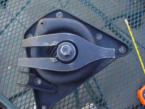
Installation will require removal of a steel ring in the upright. This ring is for the original ball-joint rubber boot retaining clip. Removal of this ring requires precise application of force with the utmost levels of accuracy: whack it out with a hammer and screwdriver. Once this is done, the XJ40 ball joint simply bolts in place of the old assembly.
11.4 - Castor and Camber Settings Explained! ( Scott/Saltwick/Westneat/Grant,
December 8, 2005
)
Castor & Camber explained
Lee Scott asked on 12/07/2005:
I got the front end aligned on the 420, which took care of my tire
squeal issue.
The report I got from the tire shop after it was done says :
camber: 1.1 degrees on the left, .5 degrees on the right
caster: -.8 degrees on the left, -1.6 degrees on the right
toe: .05'' on both.
Then there's this:
cross camber: .6 degrees
cross caster: .9 degrees
set back: .27 degrees.
What is cross camber and cross caster and set back?? Never heard
of these terms. What should the ideal settings be for all these
measurements? The tire shop didn't have the specs for the 420, so
he was using settings for a 69-70 E-type for reference.
Do I need to add/remove shims to adjust my castor and camber?
Clark Westneat responded on 12/07/2005 with:
Lee,
After the re-build on the 420, I mounted the front suspension back onto
the car -- did an eyeball alignment and took it down to my local guys. They
used the AllData specs for the 1969 XJ6 Series 1. We ended up having to
remove and replace shims on the "cage" for the suspension as well as the
wheel alignment. They used a laser alignment tool to make sure it all
aligned properly. It has been about 35,000 miles now and I still have
straight wear on the tires and no mis-alignment
I believe the cross camber and set-back is the relationship to the rear
alignment -- but I could be wrong.
Paul Saltwick responds on 12/08/2005 with:
Hello Lee,
The specs for your car are:
Camber: 1/2 degree +/- 1/2 positive
Castor: 0 +/- 1/2 degree
Toe-in: 0-1/8''
Your camber is (almost) within spec, but far from ideal if you are
running radial tires. It is normal to run more positive camber on
the left, around 1/4 degree, to compensate for the crown in the
road. 1/2 degree negative camber will give your car more grip and
better turn in with radials, at the expense of more inner tire
wear. You add shims to the top wishbone to get more negative
camber.
Your castor is out of spec. You never want negative castor. If
you run +2 degrees, the steering will feel better and self center.
There should be 8 shims and a packing piece with the upper ball
joint assembly. You adjust the caster by swapping them from side
to side.
Toe is OK.
Lee Scott responds back on 12/08/2005 with the following:
Paul,
Thanks for the info. If I understand you correctly, what I need to
do is move one or more of the shims from the back side of the upper
ball joint to the front side to adjust the caster in the direction
it needs to go? Any rough estimate on how many degrees each shim
swap will change the caster measurement?
Paul Saltwick responds on 12/08/2005 with:
Lee,
1/4 degree for each 1/16'' shim. Measure the shims with a caliper,
there are several different sizes for the camber adjustment and
they often get mixed up. Moving shims from the rear to the front
increases positive castor. The shims are slotted and you should be
able to lift up one side, after you jack up the lower ball joint
and loosen the upper ball joint bolts. If you have never shifted
the camber bolts, they often become frozen and heat, penetrating
oil and patience are needed. I recommend replacing them and using
anti seize if/when the subframe is out of the car.
Gary Grant adds in on 12/08/2005 with:
Cross caster is merely a measure of the difference between the
caster value on the right wheel, and the caster value on the left
wheel.
Cross camber is just a measure of the difference between the camber
value on the left wheel, and the camber value on the right wheel.
Set back is any front to rear difference in the positions of the 2
tire-to-ground contact patches. For example, if the RF wheel
contact patch happens to be 1/4'' more to the rear than the contact
patch of the LF wheel, there is 1/4'' set back on the RF wheel. In
other words the wheelbase on the right side of the car is 1/4''
shorter than the left side wheelbase.
And finally Lee Scott responds on 12/08/2005 with:
Thanks to all! Now I think I know what I need to know. What a great
source of info this forum is!
12 - Rear Suspension ( Chris Burdo,
May 25, 2005
)
12.1 - IRS removal ( Alastiar Lauener,
)
Yes, it is standard practice to do the brake seals etc while subframe is removed, and set-up the handbrake properly. Use coppa ease on handbrake pivots etc. Set-up handbrake before adjusting cable., but we are away ahead here :-)
For removal of subframe, I found a (long) piece of 4*2 to push through the subframe as it is lowered, and lever the rear down, to stop it from tipping forward. It is very front heavy.
1st remove grease nipples from bottom of hub-carrier, otherwise they will get broken off! Note shims between diff and drivehshaft, this is your wheel camber. There are shims at inner end of lower arm, shims for bearing set-up on the wheel bearings and on the lower fulcrum on the hub carrier.
Take your diff to a shop to be done, it probably isn't worth the time (unless it is OK of course).
All the other parts (and I mean every bearing and seal), UJs, arm bearings etc are cheap, and worth replacing. A good rear end makes the car very driveable :-) Some UJ's have grease nipples, some don't.
The most difficult is the wheel bearings, The removal of inner race of the outer bearing on the hub (as opposed to aluminium hub carrier), is a b*****d whether steel or whire wheel hub, and may need shop help, depending on what you have access to. I have known it fall off, which probably means the hub is useless. everything else can be drifted, I used a hydraulic press.
On setting up, you must understand how the end float of the hub bearings works, you do not need the special tool referred to, it is just a spacer of an exact dimension (50 thou), you can use any spacer as long as you measure it. You cannot tighten the rear hub bearings just by doing up the big nut tighter. The endfloat is governed by a spacer and shims. Don't believe anyone who tells you otherwise. The book says shims are obtainable in 3thou sizes, but I have seen them in 2 thou sizes
The preload (as opposed to float) on the hub-carrier lower bearing shaft. When you drift out the lower shaft, use a dummy shaft. If you dont, there are thin shims in there in the centre, which will get dislodged otherwise, and then mangled as you push a shaft through. The taper bearings in here often have dried up with rust, as the seals can be poor, and the water gets in. Also, the bearings only revolve by a few degrees by comparison to normal bearings.
If you are buying in kit form of parts, beware there are two sizes of outer oil seals for the bearings, changeover 1B5166, 1B25707, 1B55701, 1B78500 depedning on 3.4/3.8/LHD/RHD.
Shock absorbers/springs can be done any time, and the set-up is really a personal preference.
13 - Brakes ( Chris Burdo,
June 7, 2005
)
13.1 - Rear Caliper removal for the S-type ( Frank Benschop,
)
1. Disconnect as much of the brake lines as possible. This makes access better. This caused me the most trouble. It took me over an hour to loosen one connection, the flexible line at the T. All others needed some heat on the workbench.
2. Undo handbrake cable
3. Undo handbrake locktabs and bolts.
4. Rotated the handbrake calipers over the discs to the back and take them out.
5. Remove the bottom plate of the differential to gain some access and 'sight'.
6. Unbolt the caliper bolts. The top bolts from the front, the bottom bolts from the underside and/or front. You need a spanner with narrow sides (Am I clear? I am not refering to the wrench thickness). In general you are able to turn 1/2 a flat (1/12) at a time so you need to turn around the spanner all the time. But we have this all the time, haven't we? Sometimes, I was applying force the the differential casing instead of turning the bolt. It is difficult to see or feel. This calls for a smaller spanner or other angle.
7. Drop the calipers slightly. Pull the top of the caliper through the front opening and remove them through the front
13.2 - Airleak in Servo system ( Peter Smith,
June 17, 2005
)
Get a long piece of heater hose or something similar, put one
end to your ear and hunt around for the leak with the other.
If you can hear it just standing there you should be able to
locate it more precisely in a few minutes.
Then, if it is rubber hose, take a pair of vise grip pliers and
clamp off the vacuum hose from the manifold. You can drive and
brake fine without the servo boost and you can adjust your
carburetors in peace and quiet, a deal with the servo later.
As to the servo, if the leak is in a hose, replace that, if it
is in the servo you will have to take it out and get it rebuilt.
There is a diaphragm in the big end of the servo, early models
had a rigid plate with a seal around the edge (leather first, rubber
later) and later models had a flexible rubber piece. I would
look there first. The end of the servo screws off, you need special
churchill tool Number (X?X?X) or else a piece of plywood with 3
holes drilled into it to fit over the mounting bolts on the big
end of the servo. A little penetrating oil and maybe tweaking the
cover will let you get it open without too much trouble.
13.2.1 - Signs of a Fluid Leak in the Servo System ( Sandy Cameron,
October 13, 2003
)
Before you get too serious about a blown head gasket you might investigate
the possibility that the white smoke is brake fluid burning after it got
sucked into the intake manifold through the vacuum line to the brake
booster. This happened to me and I was ready to pull my hair out until I
noticed that the brakes were soft and fluid was disappearing but not leaking
onto the ground. Some one in the group suggested that brake fluid burning
looks a lot like anti freeze. Worth checking out. My brake booster vacuum
chamber and reservoir had about a litre of brake fluid in them altogether.
14 - Wheels and Tires/Tyres ( Chris Burdo,
June 7, 2005
)
14.1 - Wheels and Tires for Saloons ( Chris Burdo,
June 22, 2005
)
Tire information for Saloons
One of the more popular questions that appear on the Saloons list is in regards to tires.
I’ve put together the following information as an informational guide in regards to the proper tire sizes for each model.
General Information
From Greg Bernier regarding the safety issue of mixing of radials and cross-ply tires:
You absolutely cannot mix radials and crossplies, in any way. I know from
experience. I unwittingly put radials on the front of a 1974 Mercury Comet I
once owned (it had crossplies on the rear). At speeds over 45 mph the car
would wander and even swerve. It was totally unsafe on the highway. Knowing
no better, I thought something had happened to the front suspension, and did
work on that. No improvement. Finally somebody clued me in: "You NEVER mix
radials and crossplies".
From: Eric Hutchinson, Wed, 26 May 2004 regarding wheel sizes:
“the JCNA Rule Book in Appendix B lists 4 1/2x15 for the MKI, 5x15 for the MK2 and 5 1/2x15 for the 420.
Each with 6.40x15 Roadspeed for rubber. The MK2 and 420 also show the 185HR15 for later models.
There are 5 1/2 inch rims listed as standard for 240, 340, 3.4s and 3.8s also.
MKVII-IX – Tire size 6.50 x 16 as supplied from new.
From Tom Brady:
I am presently running tubeless radial wide white radial tires (215/70R16) obtained from Diamond Back Classics
in South Carolina. I have a set on my 59 and 61 MK IXs. The 215/70R16 closely matched the diameter
and width of the 6.70/16 tire but has a better contact patch on the road since it is a radial.
Handling is like a modern car with radial tires.
From Greg Bernier:
Why not use 6.50-16? There are lots of brands to choose from. According to the original Mark IX Owners' Manual,
it lists the correct tire size as 6.50/6.70-16. It works fine in JCNA judging. I use "Lester" tires.
Universal Tire and Lucas Tire both carry them.
I have been running Lester 6.50X16 bias-ply tires on my Mark IX for
15,000+ miles. I have driven long highway distances at speeds of 70-75
m.p.h., and, aside from having the normal characteristics associated with
bias ply tires, they have been very satisfactory. I have run in JCNA slalom events
with times in the low to mid 50 second range, and the tires have been fine.
If I decide to put whitewalls on my DHC, I will go with the 6.00X16 Lesters.
Just reporting my own experiences with a brand of "vintage" tires currently being sold. (No affiliation with any tire mfrs. or sales companies.)
From: Dave
I just went into the garage and measured the height on my 1960 Mk IX.
It sits on 6.50 x 16 straight ply tires ( as originally specified)
The height from the ground to the underside of the frame by the drivers door is 8.5"
If I measure from the ground to the underside of the front cross member it is 10.5"
MK1 - Tire size 6.40 x 15 as supplied from new.
From: Eric Hutchinson, Wed, 26 May 2004:
I have a question on this subject. I'm looking to replace the tires on
my 59 MKI. Lots of options and I'm curious what others have used. I'm
looking for something in a 185x15 that will also fit in the spare wheel
well. My MKI is original/unrestored and I don't want something that
looks too aggressive if possible. Something with the look close to the
Roadspeed would be preferred. Would I be foolish to consider a bias ply
6.40x15 if I found one?
MK2, 340, 240 – Tire size 6.40 x 15 as supplied from new.
From Jack Verschuur:
It is my understanding that 205/70 on wire wheels cannot be fitted with the standard spats, you'd need to get the 'sports' spats, modeled on the Coombs rear arches, sort of. 195/70 has a smaller rolling circumference than the standard tyre.
Since you're in Holland, Vredestein make a perfect radial tyre for the Mk2, which can also be fitted with the standard spats.
From GNB
I am running Dunlop Narrow white wall tyres which are 205 X 75 X 15
From Mike Eck:
I have 205/70R15s on my MK2 and they don't rub the spats but on hard cornering or bumps they seem to
rub the front fenders using the original wire wheels.
From Gregory Andrachuk, June 7th, 2005
I recently bought a set of tires for my Mark 2: 15HR15
Universal Sport tires from Universal Tire; they have a 5/8 inch white band
and the tread pattern is identical to the Dunlop Sport tires; price for
5 tires: $895. Beautiful tires; I have not fitted the yet.
From Paul Saltwick, August 5, 2005
There should be many posts on this in the archives. XJ-6 wheels
are the same bolt pattern as MK2 wheels, but the backspacing is
different, and changed again with the XJ-40. The MK2,S,420
steel wheels are 15X5,4 inch backspacing, with a 5 X 4.75 bolt pattern
(same as GM). XJ-6 steel wheels are 15X6 with 5 inch backspacing.
The additional backspacing moves the inner edge of the wheel in
And helps with fitting a wider tire in the rear, but fouls the ball
joint, tie rod, wishbone in the front. You need to use a 1/2''
spacer and longer studs to fit XJ-6 wheels to the front.
Sterling Forsythe wrote on August 6,2005
I am running the Series 2, XJ6 wheels on my 1967 MK2
with Goodyear Wrangler 195-75R-15...... or at times the
Uniroyal Tigerpaw 195-75R-15 which tyre may now be out
of stock. No problems getting the Goodyear at the moment
though.
I've fitted the longer threaded studs on the front hubs and
also use washers to clear the ball joint, tie rod, wishbone
in the front to prevent rubbing. Some further refinements
were necessary at first to preserve the full turn steering
radius movement. I have had this setup since 1997 as
a daily driver.
MKX/420G - Tire size 205 x 14 as supplied from new.
From Viejo:
The 420G I am buying has 215-14 tires on it now. The specs list 205-14 tires.
From Rick Cusack:
I'm a little late on this, but I replaced the 14" wheels on my 420G with 15"
wheels from a Series II XJ6. They look great, handle beautifully, and are
much more in keeping with the profile of the car.
420/S-Type – Tire size 185 x 15 as supplied from new.
From Clark:
I am running 205/75-15s on both my 1967 S-Type as well as my 1967 420.
As a matter of fact, I ran a 215/75-15 on the rear of the S-Type that came
off my 1988 XJ40 when the tyre went flat on the S-Type. So I know for a
fact they will fit the 420 and the S-Type. Both these cars have permanent
"spats" I will admit the 215s were a bit close and had to be persuaded to
go on.
THIS may be the difference, however. None of my cars run wire wheels.
I do not believe that you can get a 205 over the splined hub for a wire
wheel on any of these cars -- although I may be wrong.
In terms of clearance on the running, I have plenty of clearance on both
the front and rear of the car -- even under heavy load.
I run either Continental or Bridgestones on all my vehicles.
This includes my Jags. When I first got my 1988 XJ40 it was running
speed rated Pirelli P-4000s. It took me about 2 weeks to decide I would
never buy a Pirelli tyre again. They wear terribly and if the car sits for
more than 3-4 days you get a flat spot that takes a LONG time to drive
out. If in fact you DO buy the Pirelli's you MUST make sure they are all
manufactured from the same plant. They will have the plant of origin molded
right in the side of the tyre. On the tyres I run, I make sure they are
rated at least 400AA (360AB is acceptable as well) for wear and heat.
As for size. I have the steel wheels as well on both the 420 and
the S-Type. Both cars are running 205-75/15. These tyres will all fit the
rims with no problem. I have found the wider stance has made for better
handling and ride. I have a little over 10,000 miles on the 420 tyres and I
am really pleased with them. Anything wider and you will have a terrible
time getting the tyre past the "spat". As it is, I carry a 2 x 12 and a
scissors jack in order to lift the car high enough to bring the tyre down on a
vertical plane to clear the hub in the rear. The front will very rarely rub
when I make a right hand turn into my inclined driveway at too rapid a speed.
It is the only time I have heard it.
If you have wires -- this is probably the problem
From Jack Verschuur:
Just as an aside, I had 205/70 Dunlops on my 420 on steel wheels, which
worked a treat. Yes, the rears were a pain to change. No problems at the
front with the standard wheels, but with XJ6 wheels it didn't work without
spacers.
From Paul Saltwick
You have to consider the backspacing of the wheel (distance from
rear edge to hub face) when increasing the width. You can fit
wider wheels to the rear of an S/420, but they need to have more
backspacing, and you may have to remove the bumpstops. For
example, the stock 5X15 inch bolt on wheel has 4 inches of
backspacing and the stock Jaguar 6X15 wheel has 5 inches of
backspacing. This moves the wheel closer to the center and the
outside edge of the wider tire winds up in about the same place.
It is very much a trial and error fit with the S/420 and some 205
tires have wider sidewalls than others. The stock Jaguar S/420
wheels are 5 inch wide wheels, anyone that tells you otherwise
doesn't know how to measure wheels. If you can fit 205/70's on your
car with stock wheels, that is about the limit. Unfortunately, if
you look at the tire MFG's specs, most speed rated radials (above
SR -112 mph), including Michelin, are only approved for 5.5 inch
and wider wheels. The Pirelli P4000 is one exception, and that is
why it is popular with E Type owners with 5 inch wheels. Most of
the high performance rubber in 205/70 and 205/65-15 is rated for
5.5'' and wider wheels.
From Paul Saltwick:
Most of the available 185-15 tires are made for taxis or very
expensive. If you are keeping the stock 5 inch wheels, Pirelli
P4000 in 205/70-15 are the best value/performance, if you can fit
them in the rear without rubbing. I couldn't and went to 205/65-
15's on 6 inch wheels, which transformed the car more than all the
poly in baloneyland.
From John Quilter, June 7th, 2005
The Michelin 185X15 red stripe tire is still available as this
was the standard fitment on the TR6. They are pretty pricey now
though and may be reproductions of the original. I believe the aspect
was 80 although you should not notice any real difference to use 75.
I found some Bridgestone 195X15 75 and these were a good fit with
out rubbing on the front fender lips on my 1965 S TYPE with disc
wheels. They were reasonably priced at about $75 about 5 years
ago. They don't however have as good a wear rating as the
Michelins.
From Iain Buxton, June 7th,2005
Special tires are always available from Diamondback. They
are on the web and they will go out of their way to
accomodate you.
Your original ratio was 185/75R15 as I recall giving a tire
size diameter of about 25.9 inches. Go to
http://www.powerdog.com/tiresize.cgi to calculate this for
different tires. Match this overall diameter so you do not
alter the gear ratios relative to tires and to keep speedo
accurate. Width (185) is limited to an absolute max of 205
on the 'S' due to clearance on the rear fender but I would
not go more than 195 or you will get rubbing on the fender.
The wider the tire on the stock wheels the more you will
limit the turning radius in the front somewhat.
Tire Rack has the Goodyear Eagles with that period whitewall!
14.1.1 - Adding Coombs Arches to a 420/S-Type ( Iain Buxton,
May 26, 2005
)
Modifying the S-type/420 rear wheel arch,(Coombs style)
From Iain in Reno: (In regards to installing Coombs wheel arches in the S-type/420)
Well it seems to me that the Rear Wheel Reveal is in order
here! I have some pictures on the photo gallery showing the
result. It is interesting that the original 5 inch wire
wheel with a 195 tire looks totally lost in that rear space
when the Coombs Spats are welded in on the S-Type!
I have new 16 inch by 6 inch wheels and 225/60R16 tires and
that gives the same overall tire diameter as original.
14.2 - Wheels and Tyres for the S ( David & Patricia Reilly,
December 27, 2005
)
As Editors of the International 'S'-type Register Newsletter, we
were assisted by Longstone Tyres in Bawtry, South Yorkshire,
England (www.longstonetyres.co.uk)in producing an article on
'S'-
type tyre choices. Following is our article:
For an 'S'-type Jaguar I would choose between the 2 best tyres,
depending on what is wanted out of the tyre. For originality I
would fit the Dunlop, if I wanted performance and longevity out
of my tyres I would fit the Michelin. We are always pleased to
provide a free fitting service to all our customers and provide them
with a cup of tea while they look at our well campaigned vintage cars.
185HR15 Dunlop SP Sport (Aquajet) is quite a famous extremely
period tyre, one very similar to this was fitted by Jaguars to
the later 'S'-types, E-types and other cars of the late 60s. (Ed:
Note that while an ‘SP’, the tread is different from the original
‘SP41’.) 185HR15 Michelin XVS-P is a fantastic tyre developed through
racing. Michelin brought out the first tyre with an asymmetric
tread pattern and carcass in 1965. The XVS was developed as an
upgrade to enhance the handling of cars of this period. In
Longstone's opinion, ''You can’t get a better tyre
in this size''. 185SR15 Michelin X is the perfect tyre as an alternative to a cross-ply tyre.
In 1946 Michelin developed the first radial tyre to enhance road holding and longevity of tyres.
A lovely period tall tyre with rounded sidewalls and thin tread but in the case of an 'S'-type
an insufficient speed rating of 112mph.
185HR15 Avon TurboSteel is a good quality British tyre fitted as
the radial alternative for many late ‘60’s cars
including Aston Martins. 185HR15 Vredestein Classic is low cost but not as cheap as the Michelin X.
It also has a more modern looking tread pattern.
Cheers,
David & Patricia
15 - Body and Exhuast System ( Chris Burdo,
June 7, 2005
)
15.1 - Jaguar/Daimler PPG/Ditzler paint codes ( Richard Faller,
)
A while back I asked the list for info on the Dana 44 and the jag rear.
The replies inferred that they had heard they were the same but no first
hand knowledge.
I have just completed changing the ratio on a jag IRS unit that came out
of a 68 420G from 3.54 to 3.07. I bought a used gear set with the carrier
from e-bay for $15, US variety from an international scout. I also bought a
jag dana 44 set up kit , about $75(precision gear).
The pinion from the US variety is slightly different. The jag unit has
10 splines, the US pinion has 30. Because the jag drive shaft rear universal
joint is the same as some Chevy's, and the Dana 44 is used in some Chevy
trucks, this problem can be solved. Put a spicer # 2-4-2461X yoke on the
pinion and remove the companion flange on the rear of the drive shaft. The
rear u-joint is held to the yoke with u-bolts Napa 329-10. The rear joint is
a Napa 369.
The ring gear is also slightly different. The jag unit is tapped for
7/16 NF. the US unit is tapped for 3/8 NF and this is the size of the bolts
supplied by precision gear. Grainger sells motor bushings for 3/8 to 7/16 to
take up the slack. You can re-tap the ring gear to 7/16 NF, or tap in a
couple of allen screws at 180 degrees to locate the ring gear and let the 10
bolts hold things together.
The carrier came with the gear set so I thought I may as well look an see
if this would work. Forget it, the axle splines are different.
The diff setup kit was almost perfect. The kit came with both bearings
for the pinion. The inner one was right, the outer was too small. I had to
destroy the inner bearing to get it off te used pinion. Also the pinion
depth shims were mangled when I drove the inner bearing race out. New shims
are in the kit.
Everything else went fine, measure the old pinion shims and with the
etching # on the pinion determine what you have to put back. This will
eliminate the step requiring a special dana 44 tool. The pinion drag is
adjusted by the # of shims between the inner races. It is set up much the
same as a wheel bearing with no adjuster nut and cotter key, rather shims in
the middle and the pinion nut at 100+ft/lbs.
The yoke comes with a dust protector to make the pinion seal last
longer. If you want to keep it you will have to grind a small amount of the
diff. casting away or simply drive the dust protector off the yoke.
You will need a dial indicator and magnetic base(backlash), torque
wrench(pinion nut), a big puller(companion flange), regular tools and lots of
patience.
If I knew then what I know now I would buy a new gear set for a dana44
and a diff set up kit for a Jag. The dana 44 gear set is about $150, one from
a jag supplier with the 10 spline pinion it is over $400.
15.1.1 - Jaguar Paint Codes in BASF Glasurit ( Iain Buxton,
January 19, 2006
)
Jaguar Paint Codes in BASF Glasurit
Colour……………………………………Year Range…………………..Glasurit #
Battleship Grey……………………….1947-56……………………..JAG-25447
Birch Grey………………………………1947-56……………………..JAG-25448
Cornish Grey………………………….1957-63……………………..JAG-7399
Dove Grey…………………………….1953-56……………………….JAG-25449
Silver Grey Metallic…………………..1959-68……………………..JAG-701
Signal Red……………………………1968-79……………………..JAG-301
Opalescent Gunmetal……………….1959-64……………………..JAG-7402A
Lavender Grey……………………….1947-56……………………..JAG-25450
Warwick Grey………………………..1964-72……………………..JAG-703
Dark Blue……………………………..1961-79……………………..JAG-529
Regency Red…………………………1968-91……………………..JAG-302
Opalescent Dark Blue………………1959-64……………………..JAG-7409A
Opalescent Silver Blue……………..1963-68…………………..JAG-7410S
Cotswold Blue………………………..1957-64……………………….JAG-7411A
Indigo Blue……………………………1957-64……………………….JAG-7412A
Light Blue……………………………..1968-72……………………….JAG-507
British Racing Green…………………1949-1975………………..JAG-602
Sable………………………………….1969-76……………………….JAG-803
Opalescent Dark Green……………1959-67……………………..JAG-7416A
Sherwood Green…………………….1957-68……………………….JAG-605
Carmen Red………………………….1958-69……………………..JAG-303
Imperial Maroon …………………….1958-71……………………..JAG-7420
Opalescent Maroon……………………1962-66……………………..JAG-7421A
Ascot Fawn…………………………….1968-72……………………..JAG-105
Old English White…………………….1957-70……………………….JAG-106
Honey Beige………………………….1967-70……………………….JAG-101
Pale Primrose…………………………1964-75……………………….JAG-104
Bronze Metallic………………………..1959-62……………………..JAG-25458
Willow Green…………………………..1967-72……………………….JAG-603
Golden Sand Metallic………………..1962-68……………………..JAG-802
Fern Grey…………………………….1973-78……………………….JAG-7431A
Lavender Blue…………………………1973-77……………………….JAG-508
Heather…………………………………1973………………………………JAG-308
Azure Blue……………………………1973-75……………………….JAG-7435A
15.2 - Refinishing Saloons Woodwork ( Larry Martz,
March 1, 1996
)
REFINISHNG EARLY JAGUAR WOODWORK
This piece is written (3/96) because I've received numerous compliments and questions about the wood finish in my original-condition '59 Mk IX -- not a super-high gloss over-restoration; rather, a deep "glow" that emphasizes the veneer patterns and colours. In fact, Jaguar did all the wood pieces by hand in the old days without all the modern Varathane, etc. Larger pieces were signed and dated on the back by the craftspersons (not just assembly-line workers!) who created them; they were proud of their work, as they should have been.
Also -- be aware that the larger veneer pieces had the veneers matched car by car, so changing a piece nowadays will result in a different veneer pattern.
If you follow these steps in order, you can achieve a finish that closely matches what the wood looked like on a new car. This process takes a lot of your time and some patience (trying to rush will screw the job up), but it's not really expensive.
(1) Analyse all the visible wood trim pieces for damage to the veneer. I recommend that you photograph it in place, close-up (macro lens, etc.), using small post-it notes to identify each piece. Take notes, piece by piece, on any damage you find.
(2) I recommend that you proceed from here on piece by piece, rather than removing all the wood at once and winding up with a bunch of unidentifiable lumber. If you want new mounting screws, take the originals to a good hardware store and match them -- cheap! For each individual piece, follow the Refinishing steps.
REMOVING/INSTALLING WOOD PIECES
I recommend that you follow this removal/installation sequence, from rear to front:
(a) Strips surrounding windows -- all are mounted by wood screws, accessible under the door sealing rubber (just lift it up carefully with a small screwdriver, and unscrew the screws). Start with the right rear piece, which wraps around the rear vent window (2 or 3 screws). Refinish it as outlined in REFINISHING below, then reinstall it. Then, remove the long upper strip over the door windows( 5-6 screws); refinish and reinstall. Then, remove the short front strip along the side of the windscreen; refinish and reinstall. Repeat this sequence for the left-side window surround strips.
(b) If your car has the wood trim on the top of the front seat(s), open the picnic tables and remove the wood screws (bench seat, 4 screws; bucket seats, 2 screws per piece), then remove the trim pieces. Refinish and reinstall.
(c) If your car has the picnic table(s) behind the front seats, find the wood screws (tables open) and remove the assemblies. Disassemble, refinish wood, reassemble, and reinstall.
(d) Doors -- remove the capping piece from each door (4 screws with cups), then lift out the larger panels upward (they clip into the door). Refinish and reinstall.
(e) Upper windscreen surrounds, 2 pieces -- remove the wood screws (4 with cups), refinish and reinstall. Note the chrome centerpiece, Mk VIII and IX; clean up or have it rechromed before reinstalling wood.
(f) Upper dash (carries the rear-view mirror, ashtray on Mk VII, passenger grab, Intermediate Speed Hold/Overdrive switch if there, brake warning light if there) -- remove the upholstery trim pieces below the panel, remove the ISH/OD switch and BWL if there by pulling the switch/light (unscrew chrome hold pieces) and disconnecting the wiring (tag wires and switches/light with tape to make reconnection easy), remove the left/right bolts holding the panel, remove the panel. Remove the mirror, ashtray if there, and passenger grab. Refinish, replace the mirror, ashtray if there, and passenger grab, and reinstall the panel, replacing the ISH/OD switch and BWL if there.
(g) Instrument panel -- remove upholstery panels under the panel, all knobs and switch handles (a small nail works well to push the spring holders in), the ventilator handle (screwdriver), the two bolts at the bottom left and right, and the two upper left & right mounting screws (by hand). Remove the panel. Refinish and reinstall.
(h) Compartment doors, left & right -- remove by unscrewing 4 small brass screws per door in the hinges. Remove hinges (2 small brass screws per hinge), small handles (1 screw/handle), and the lock on the locking door (3 screws). Refinish and reinstall the hinges, handles, and lock, but do not reinstall the doors (4 small brass screws) until after the next step.
(i) Panels behind compartment doors -- I recommend leaving these in; they're the least damaged, and the hardest to get out. Refinish (but do not strip, just sand carefully) and reinstall compartment doors.
REFINISHING
For each individual piece, follow these steps:
(a) Strip the piece. I recommend a mild stripper such as Ace Hardware #12058, Heavy Bodied Stripper. Use a 1" brush to flow the stripper on all surfaces to be stripped (the visible ones), let it sit for 10 minutes, rub it down with a biscuit of 1000 (fine) steel wool dipped in stripper, let it sit for another 10 minutes, spray it with cold water (a garden hose controllable nozzle) while rubbing with a new, dry biscuit of 1000 steel wool, dry the piece IMMEDIATELY with a terrycloth towel, and put it away to dry thoroughly. DON'T let the water stay on for any reason; it could warp the wood!
(b) Sanding: Once the piece is thoroughly dry, sand all visible surfaces GENTLY with the finest grade of garnet sandpaper (for wood). DON'T use high pressure; a pound or two with your fingers is enough. Otherwise, you might go right through the veneer (1/64" thick when new). Just keep sanding LIGHTLY until the finish is smooth.
(c) For damaged veneer: Find a GOOD woodworking place; take the damaged piece in and ask if they can supply some veneer that's close. When you find some, buy more than you'll need (it comes in rolls, and they'll cut off as much as you want). Where the damage is, find some veneer lines on the wood to be restored that surround the damage, use a razor knife to cut along those lines, lift the damaged piece out, and find a place on the new veneer that closely matches in terms of lines. Cut it out of the new veneer using the piece with the damage as an exact match, and glue the new piece in using Elmer's Carpenter's Wood Glue -- very sparingly; you just need to cover the surface. Clamp the piece using terrycloth under the clamp(s) so as not to damage the wood, and let it set at least overnight. Then, sand again with the fine garnet paper along the joints of the new piece until you're satisfied with the smoothness.
(d) Staining: I've had great success with Watco Danish Oil Finish in medium walnut. Once you're satisfied with the smoothness of the wood overall, use a small paintbrush to detail the joints of any veneer repairs with Watco, and put the piece away safely at least overnight. Then, rub Watco into all visible surfaces using a terrycloth washcloth, drying with a clean washcloth when it's totally covered. You'll be amazed at the restoration of colour, but you're not done yet! If there are any places notably lighter than the rest, put more Watco on them and dry. When you're satisfied with the colour, put the piece away safely at least overnight (2 or 3 days would be better).
(e) Waxing: Now, put a thin coat of Watco Satin Wax Dark on the visible surfaces. Let dry for 10 minutes (more if it's cold weather), wipe with a clean terrycloth washcloth until dry, then polish with a clean terrycloth towel. For additional luster, use the satin wax as a lubricant while rubbing with #600 wet-or-dry sandpaper, let dry for 10 minutes (more if cold), then polish as above.
For even more luster and lasting protection: Apply a thin coat of Minwax Paste Finishing Wax to all visible surfaces, let dry for 20 - 30 minutes (more if cold), then buff with a terrycloth towel. If you've followed the above procedures, your wood will glow! Use the Minwax every 3 - 4 months as continued protection for your now beautiful, classic wood.
15.3 - Central Locking/Power Windows for a MK 2 ( Neil Syder,
June 17, 2005
)
I use my car daily and therefore wanted to make some practical
modifications whilst keeping the car looking standard but I can
see myself that most will think I have got carried away. With
regards to what I have done to my car I guess it has come as a
bit of a surprise to me as much as anyone
–
(1) Whilst walking around Maplin electronics in my local town
(Warrington, UK) I spotted a universal central locking kit for
sale for Ł20. I thought why not and if I cannot fit it I can sell it
on E bay. This was late December 2003. Over the Christmas holiday I
thought if I do not try and fit it now I never will and so spent
the following two days fitting it. I was shocked at how easily I
got it to work (my car is 1967 and has late door handle
mechanisms which may have helped me but I am not sure). I started
on the back doors which as it happened are the easiest as there is no
problem with the window mechanism fouling the central locking. The
front doors have to be controlled using the full length on a rod
(supplied with the kit) so that the solenoid is low down in the
door and the window can still work. I have no photos of the
installation with the door panels off to show you but will be
taking tem off again soon to fit the electric windows and will
see if I can get some then.
(2) After fitting the central locking and it working so well
I decided I wanted to have the doors lock using a key fob rather
than turning the key in the drivers door lock. So at this point
I started looking for an alarm with a locking interface on e-bay.
I am sure others will understand I would have been very happy with
a simple system but after looking for a while I found an alarm
which just sounded to good to be true. For Ł80 (I had to buy a phone
as well for this total cost) it controlled the central locking,
could start the car, connected to a mobile phone, which would ring you
when the alarm is triggered. You can also phone the car to lock
it or check it or even start it. Well I contacted people who
previously bought it to see if it was any good and they all
confirm the offer to be true. So I bought one. To fit it I had to change
the car to negative earth (I think I did this before buying the
alarm). At this point I got the clock fixed and converted to
positive earth by Mike Eck whom I feel was great value also. How
to change polarity is recorded in the archives and I followed the
advise of other members and again this was very simple 2hrs
work. I then fitted the alarm as per the instructions and did not
believe the auto start would work on such an old car (but it does – well
when cold, if the car is warm and being stood for half an hour
it needs a longer crank to get it started – I think it suffers from
mild vapour lock). To fit the alarm and make a separate wiring
loom for all the accessories took me a week or so working on the car
after work for an hour or two most nights. I was keen to have a
separate wiring loom so that I could keep the car standard and
separate at a later date if I had problems.
(3) Because the alarm had a boot (trunk) release trigger I
though I would see if I could buy a boot release system. Again
back onto e-bay and found a local firm in Warrington selling it for
Ł15. Bought and fitted – this was not so easy and took 3 full days to
figure out and fit.
(4) Next I thought I would try electric windows. Again back
to e-bay I bought some universal motors (2 first to try and see
if they were powerful enough). Fitted the motor in about 2 hrs and
it worked. It then took me another 2 to 3 weeks sorting out how I
wanted the electrics and the switch to work. Basically on the
doors I am using a spare set of door opening mechanisms (taken of a
scrap car) in the position that the window winders were. These allow
the window handle to move up and down slightly but not turn all the
way round as normal. The normal window handles still fit these
mechanisms. Connected to this mechanism are two micro switches,
which trigger when the handle is raised or lowered to send power
to the window motor. I have also bought the electric window control
switches that are used on Mk10 (it fits in the centre consol
between the seats). I am getting the wood finished to match the
rest of the car before fitting but the wiring is waiting and
ready.
(5) Finally I bought a self raise system (for the windows)
that fits onto the alarm (guess were from) and fitted that. I
know that is taking it to far………
Anyway once I have the front windows fitted I think this will be
the end of it. I am happy to say everything I have fitted has
worked without any issue since fitting and remember this car is
used daily.
15.4 - Door Seals for a MK2/420/S-type ( Tom Carson,
March 31, 2000
)

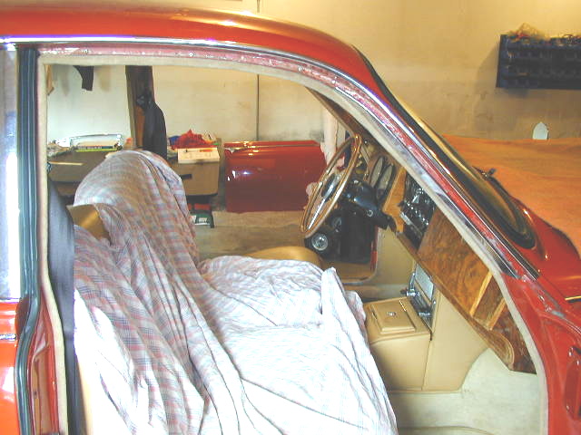
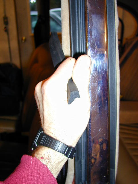
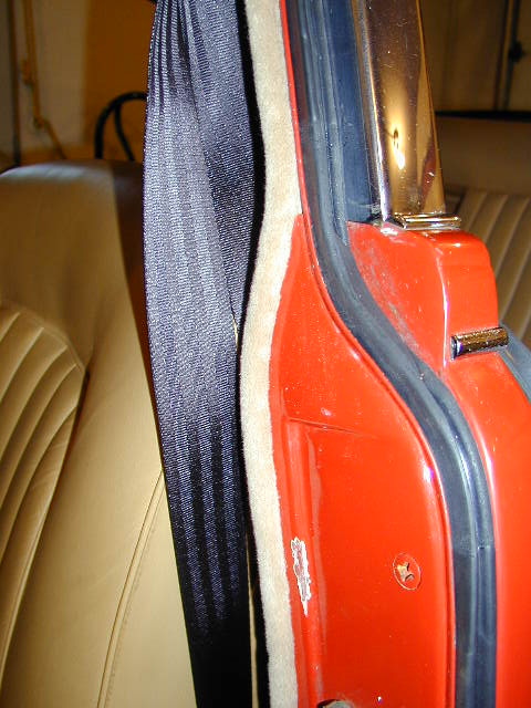
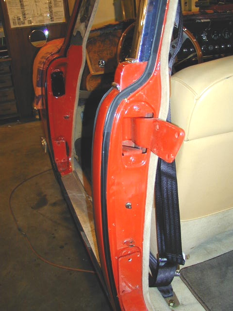
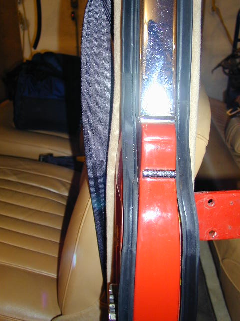
Left Side Installation
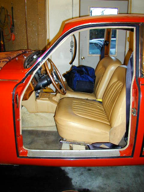
Front Lefthand Door Seals
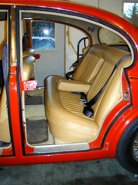
Rear Lefthand Door Seals
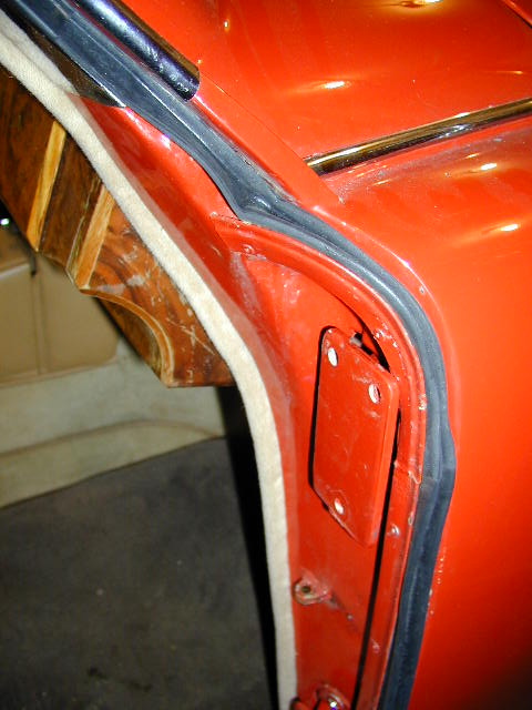
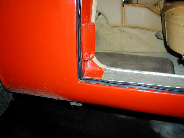
A-Post Drainage
Channel Squeezed Shut
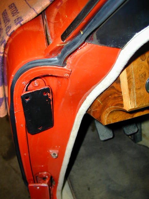
A-post drainage
route shown
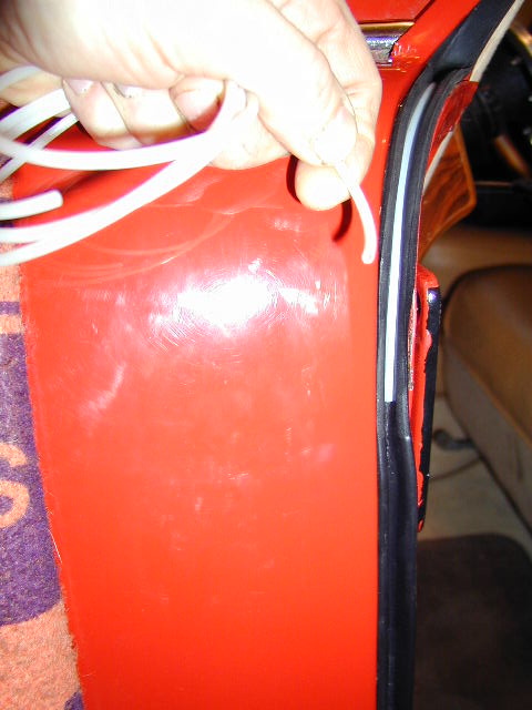
A-post drainage channel
opened up with plastic tubing
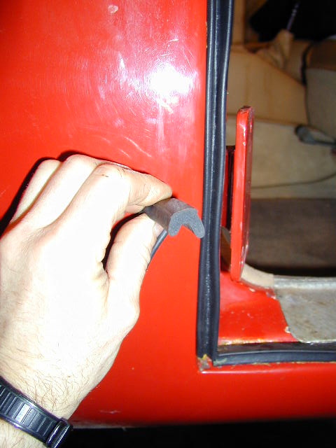
Lower A-post profile

Upper A-post profile
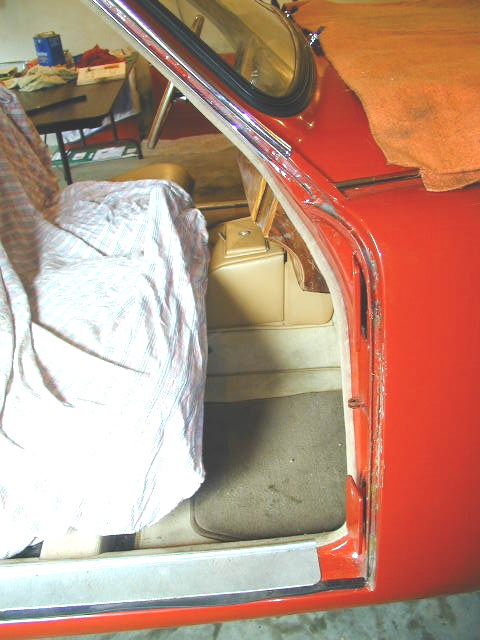
A-post front
channel before seal
A-post upper channel
before seal
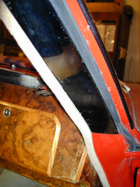
A-post upper seal
position for max extension
of sealing surface
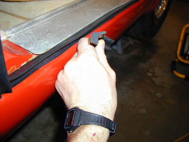
Sill profile orientation
Sill front righthand side
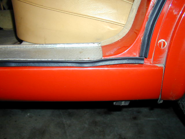
Sill rear lefthand side

Sill lefthand overview
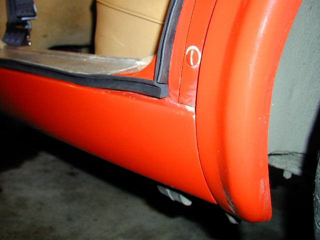
Sill rear lefthand side
Sill lefthand B/C post
Sill front lefthand side
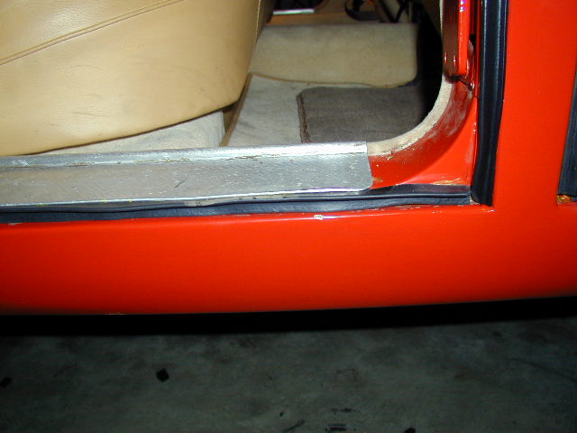
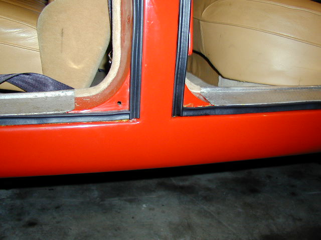
B-post profile
orientation

C-post profile orientation
my final decision although information varies

C-post lower
profile oreientation
B-post seal
installed
C-post seal
installed
B/C Post.
Note B-post drainage channel
to rear of seal
D-post righhand side. Note
drainage channel to rear

D-post righthand side,
lower section

D-post lefthand side
lower section. Note lap
for drainage
D-post righthand side looking
up from below
D-post lefthand side mid-looking to rear

Tom Carson
|
A few comments on installing door seals:
1) I have found that "super trim adhesive" (3M) does not adhere satisfactorily to the new rubber seals unless the surface of the seal to which the adhesive is applied is first roughened with sand paper and then cleaned with Acetone. If this is not done, the seals come loose within a day or so, especially if they have gotten wet in heavy rain (good old Juneau). This could be a real bummer if the seals at the leading edges of the doors come loose. I am about ready to try Super Glue as recommended by some on this list if I experience any more problems.
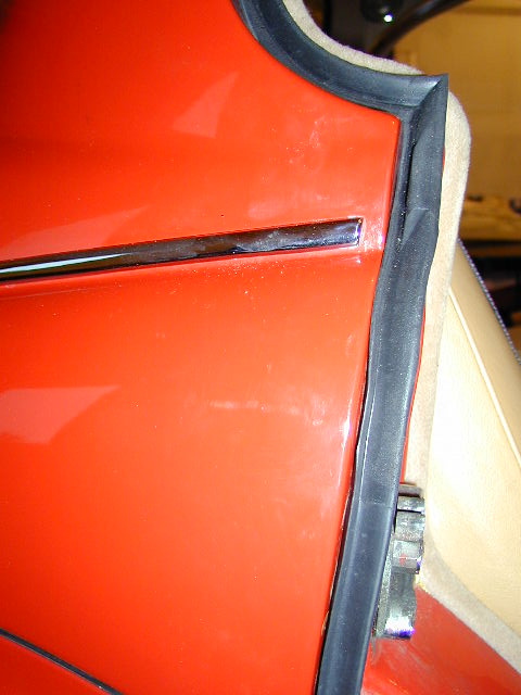
2) When installing the seals against which the window frames will close, take special care to position the seal so that the sealing "wing" protrudes out from the body to the maximum extent possible. This will allow the window frame to contact the seal more readily without too extreme an adjustment inside the door (at the bottom end of the frame where it bolts to the door). The factory used wooden shims at this point, I used a 1" hole saw and cut plugs out of PVC sheet material.
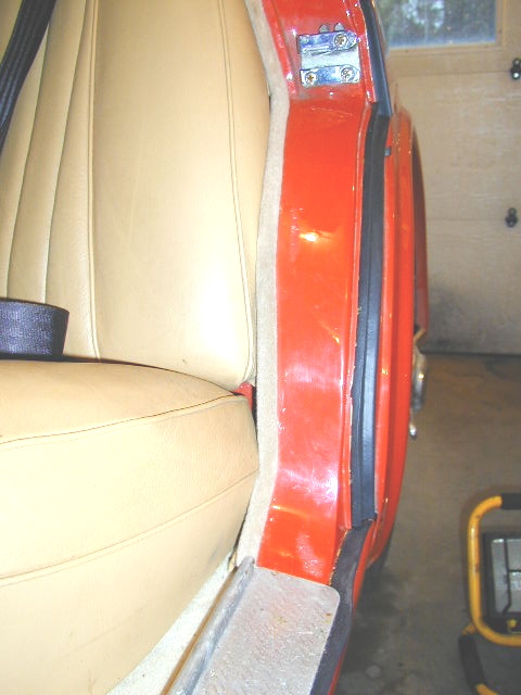
3) The leading edges of the rear doors were the most cantankerous seals to fit on my car. The bottom hinge would foul on the protruding "wing" of the seal. I finally trimmed the seal at that point so the hinge swung past the seal without touching it. Similarly, I found that as the door swung shut the top leading edge of the window frame would catch the protruding "wing" of the seal at the top of the "C" post. Had I left it that way, the seal would have been folded over on itself every time the door closed. Here I again slightly trimmed the seal to prevent such an occurance. This was necessary on only one side of the car.
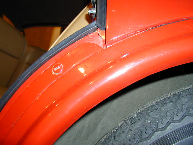
4) The factory installed a plastic sheet on each door before the door trim panel was installed. In my opinion this is a very important item because water runs down the outside of the window, inevitably gets past the squeegee (or brush as on my doors), and finally drips off the bottom of the window mechanism on it's way to the bottom of the inside of the door. Because of the shape of the door, some of the drips actually hit the inside skin of the door first. Without that plastic carefully installed and sealed on the door skin, those drips will find their way through the various holes in the inner door skin to the inside of the car, where they will cause the carpet to get wet. Carefully installed plastic sheet keeps the water on the inside of the door. I used Sikaflex 1A urethane caulk (it is sticky, seals well, stays flexible and allows the sheet to be pulled off in the future). So long as the drain holes at the bottom of the door are functional, the water drains to the outside and the interior remains dry.
15.4.1 - Door Seal Replacement for a MK2/S-type ( Jacques B,
June 21, 2005
)
I replaced the door seals on the MK2 a couple of years ago
using J.C. Whitney Stock # ADA818835T.
The profile and consistency of these seals were a perfect
match for the still intact portions of the orginal seals I
removed.
They come in 8 ft. rolls that sell for $8.99 a piece (+
shipping). IIRC, 5 rolls were needed to do all 4 doors.
I did, however, remove the original thin rubber strip in the
bottom of the seal gutters. I don't know if it would have
been thick enough to make a difference as far as door
alignment is concerned, but the new seals ''sat'' much better
without it. In fact, I never did get around to glueing them
in, and none of them has come out yet.
15.5 - MK1 Headliner Installation ( Mike Waldron,
September 29, 2005
)
It's been ten years since I put the headliner in my MK-I, here
is what I think I remember.
First; I don't recall it being all that difficult.
Second; There are wood strips along the roof line above the
doors, attached to the body with spiral nails.
Third; The metal "spike strips" are attached with screws to the
wood strips, the teeth face the wood and are on the bottom, the screw
holes are above the teeth on the top (does that make sense?). The
headliner material "pinches" between the teeth and wood. Seems like the
teeth are angled up just a little so you can push the headliner in,
but it can not be pulled back out.
Fourth; The headliner bows go through the "pockets" sewn into
the headliner and the bow ends go into holes along the roof line
above the doors.
Fifth; The rear window seal is what holds the headliner at the
rear.
OK.
Clean hands.... trying to get dirt off the headliner once it is
installed is a pain.
Put the bows through the pockets. Not all the bows are the same,
figure out where each one goes first.
Put the bow ends into the holes.
Starting from the middle (post between front and rear doors)
push the headliner material edges between the teeth and wood.
Do a little on the drivers side then the passenger side, then
move a little forward and then a little backward. The goal
being to keep the headliner centered.
You can always go back and shove a little more in to tighten the
headliner, but you can not pull it back out! I used a putty
knife to shove the headliner material in. I pulled the excess headliner
material edge out to the door frame, then held that extra material
while pushing the headliner between the teeth and wood with the putty knife.
Keep that little "flap" of material out until you are happy with the
headliner tightness, then shove it under the teeth or trim it off.
You're going to hold onto that flap so the when you shove with the
putty knife it pulls the headliner under the teeth.
NOTE: This is the official way to do the headliner at the rear
window and will insure that the window leaks... Put the headliner out
the rear window opening, install the windows seal over the headliner
material, install the window, trim the excess material hanging out the
back of the car.
But wait!
I installed my rear window before the headliner and I just put
some weatherstrip adhesive under the window seal and used a
screwdriver to poke the headliner material under the seal and
into the glue, it's still there and the rear window doesn't leak!
Install the trim pieces.
15.6 - MK2 Headliner Removal ( Tom Carson,
October 4, 2002
)
Another trip down Memory Lane. And remember the following comments pertain
to a 1962 Mark 2.
You will be performing what the manual always calls "the reverse order" of
installation. And do this carefully so you hopefully end up with a complete
old headliner to reference when you install the new one.
Preliminary to the following steps I also recommend removing the front and
rear seats and if at all possible, the carpeting. I had glue and stuff all
over the inside of the car when headliner installation was underway.
OK, the steps for removing the old headliner:
1) remove all the wood trim pieces around the edges of the headliner (this
is not incidental, but I am assuming you know where the screws are...holler
if you don't),
2) remove sun visors, rear view mirror, and the two interior lights back by
the parcel shelf (careful when removing these last two items...there's a
wood ring each light mounts to that will probably fall to bits when you
remove it..you need the old ones for a pattern),
3) remove the front windscreen complete with rubber gasket,
4) remove rear wind screen complete with rubber gasket,
At this point you will basically be ready to begin removing the headliner
proper. Observe how it is installed. If you have a digital camera snap a
bunch of images. Now begin removing it:
5) peel the liner carefully off the lip of the rear window opening (where
you will find it glued),
6) ditto front window opening,
7) work your way along each side edge of the headliner. You'll probably
find a combination of staples, brads, glue. Note all this carefully because
you'll be there again pretty soon with the new headliner, trying to achieve
a tight, wrinkle-free installation.
8) once the front, rear, and both sides are free, you are at last ready to
remove the cants (cants are the metal bows that hold the headliner up into
position). The cants are in sleeves in the headliner, and at each end of
each cant is a metal clip that fit into a bracket welded to the inside of
the body just above the door openings.
9) starting at either the front or the rear, you will now be able to grasp
the cant through the loose fabric of the headliner and actually rotate it
back towards the center to the car and downwards. Once in this downward
"sagging" position you'll be able to lift each of those clips up and out of
the bracket. Pay particular attention here!! Each cant has it's own
particular clips. The clips are NOT interchangeable among the various
cants, and the cants are not interchangeable among the various sleeves.
Keep the digital camera at hand and proceed with care. Mark everything so
you know which cant goes in which sleeve, and which clips go with which
cant.
Once you have the cants and clips free, then the headliner is also free. I
recommend laying the old headliner out on a table or flat surface, and
installing the cants and clips back into it...and make them secure so things
don't fall apart. Keep it all together until the new headliner is ready to
be installed. Which ain't yet, by the way.
There'll undoubtedly be lots of clean-up to do. The jute matting that is
glued above the old headliner is probably history. I replaced the jute
stuff with that self adhesive "black rubber" sound-deadening mat (Dyna
Matt?) above my new headliner. It worked OK, but I made the mistake of
using every piece of the mat (it's not cheap stuff!), cutting it into small
pieces to fit here and there. I now recommend against this approach. Buy
as many mats as you need, but only install it in longitudinal pieces that
span at least two cants. Even though those mats are self adhesive (and as I
recall I also used 3M spray adhesive in an attempt to achieve maximum
overkill), I have suffered some of the smaller pieces coming loose. Not too
cool.
15.6.1 - Headliner Installation for the MKVII and MKVIIM ( Alan Schultz,
July 8, 2008
)
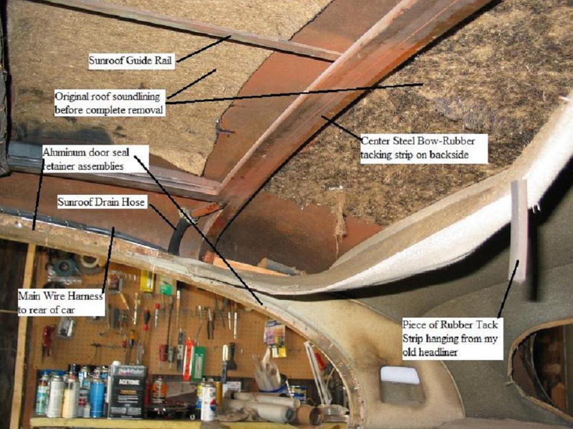
Picture #1 - Roof layout
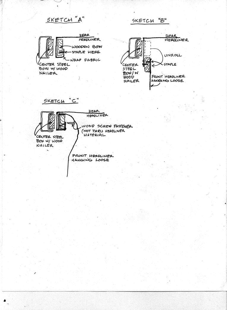
Sketches A.B,& C: Sketches of how the headliner is stapled to the wooden bow follow

Picture #2: Picture of headliner for a MKIX. Same for a MKVII
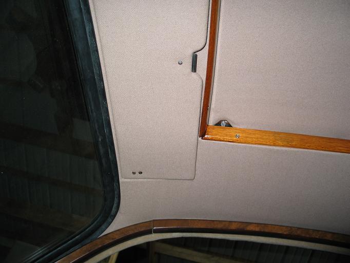
Picture #3: Headliner detail for step #19
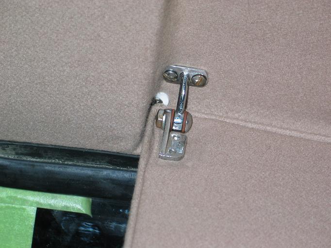
Picture #4: Sunvisor detail for step #23
|
Jaguar Headliner Installation for MKVII and MKVIIM
(May be applicable to the MKVIII, MKIX and MKX) by Alan Schultz 7/8/08
List of Materials:
1. Four (4) boxes each of medium and small size spring clips.
2. Spray can of 3M #8088 adhesive.
3. High quality sharp good cutting hand scissors.
4. Heavy Duty staple gun.
5. Box of Ľ” leg heavy duty staples.
6. Tacks similar to the ones removed when original headliner was removed.
7. Headliner materials.
8. Three or four large “C” type vise grips.
Before beginning the installation:
* This is the time to replace to rotted drain hoses for the sunroof.
It also would be best to install the new wire harness at this time (if needed).
* Check all tacking strips. They need to be in excellent condition. Replace the
strips with new plywood pieces if required.
* The nailer strip installed on the center steel bow is rubber and is very hard.
Remove it and replace with plywood or do as I did and steam bend a piece of
straight knot-free pine to conform with the steel bow’s contour.
* Add sound lining to underside of roof where desired. I used 2 coats of 3M #8088
adhesive sprayed on both the sound lining felt and the metal.
* Install the sunroof (if it was removed). The center guide rail must be bolted
to the center steel bow which will not remain accessible for long. See picture #1.
You are now ready to start installing the headliner!
1. Determine which flexible steel bow and which end of each match the mounting holes.
This is important since it determines the position of the bows when installed.
2. Insert the bows into the sleeves of the headliner
3. Offer up either bow and fasten at each end. Don’t tighten yet, leave a little play.
4. Offer up the second bow and do the same.
5. There should be excess headliner material bunched up at each end of the both bows.
Carefully cut the stitching at the ends so the bunching is eliminated. Try to snip
the same amount of stitching on each side so headliner is centered. Pull the
headliner to the sides to see if enough stitching has been cut to allow the material
to be pulled tight and sagging eliminated.
6. Now gently pull the headliner to the rear window opening. Leave the material sag
loosely. Use spring clips to hold the material at the top of the window opening.
7. Now staple the rear headliner and the front headliner to the loose wooden bow
which you should have saved after it was removed with the old headliner.
Note how it fits up to the center steel bow. Refer to the following sketches
showing the step by step procedure for completing this task.
Sketches of how the headliner is stapled to the wooden bow follow:
8. See sketch “A”. Wrap the front edge of the rear headliner material over the
loose wooden bow. Don’t staple yet. Place the wrapped bow against the center
steel bow. If there is slack pull on the fabric to tighten. Don’t pull too
hard against the two steel bows. Pull the material to the sides as well
to tighten the material. Clamp the wrapped bow to the center steel bow with
a couple vise grips.
9. Now pull the rear headliner material tighter to the rear window opening.
When the material is taunt and sag free. Place many spring clips at the
rear window opening to hold the headliner in place. Pull sides of headliner
so wrinkles disappear. If it looks good, you are ready to staple the fabric
to the wooden bow as shown in Sketch “A”.
10. Staple the fabric to the wood bow.
11. See sketch “B”. Unroll the wood bow and attach the front headliner fabric.
12. Reroll the fabric and wood bow, place on center steel bow and clamp in place.
Note: Lift front headliner material so that wood screws can be driven through
the wood bow and into the wood nailer in the center steel bow. See sketch “C”.
13. Unfasten the headliner from the rear window opening and carefully apply 3M adhesive
to the edge of the headliner. Masking areas with tape and paper to avoid spraying
areas where adhesive isn’t desired.
14. Pull headliner tight and press onto adhesive. Careful to avoid wrinkles. Put
many spring clips on the assembly and let the bond cure for several hours.
15. Picture #2 shows the rear and front headliners in place.
Picture of headliner for a MKIX. Same for a MKVII.
Pull the sides of the rear headliner to the tack strips above the rear doors
and staple. Note: I found that the 1/4” staples are only sufficient to temporarily
hold the headliner in place. In a later step, I tacked the material in place to
securely anchor the material.
16. Next is the front headliner. If your vehicle has a sunroof, the headliner will
need to be cutout for the opening. Pull the material over the opening and mark
with dressmakers marker or some such. Don’t cut on that line! Leave at least an
extra 2” of material. You don’t want to cut the opening too large and ruin headliner.
Excess material can be trimmed later.
17. You’ll need to cut at the corners of the opening to allow the material to conform
to the opening. Don’t cut too far; the material will have some stretch.
18. Pull the headliner to the sunroof opening and upwards. There should be a tacking
strip on all four sides of the opening. Staple the fabric to this tack strip.
Note: I found that the 1/4” staples are only sufficient to temporarily hold the headliner
in place. In a later step, I tacked the material in place to securely anchor the
material.
19. Work your way along both sides and staple the headliner to the tack strip above
the door and the tack strip on the sides of the sunroof opening. As you work
along check to make sure the headliner is tight and without wrinkles. See Picture #3.
20. Where the headliner is to be attached to the “A” pillar. Use a strip of double faced
tape to hold the material to the steel pillar.
21. Staple the headliner at the front of the sunroof opening.
22. Now pull the material to the front upper edge of the windscreen opening and spring
clip in place.
23. If you have recessed sunvisors, I wish you luck. I had to screw the corners of the
material in place with #4 stainless steel screws and finishing rings. See picture #4.
24. Once you are satisfied with how the front headliner looks at the “A” pillars, recessed
sunvisor pockets, the sunroof opening and the front clipped edge, you are ready to begin
using the 3M adhesive to attach the material.
25. Apply adhesive to the inside edge of the wind screen opening only and headliner fabric.
26. Stretch and stick to the inside edge of the opening. Clamp with spring clips and let cure.
27. After curing remove the spring clips and carefully trim the fabric so there is only about
an 1/8” of fabric that will fold over the windscreen lip.
28. Apply 3M adhesive to the remaining 1/8” of fabric and the outside lip of the windscreen
opening.
29. Fold over and clip in place.
30. Go back over the installation and remove any wrinkles. Try the wood trim moulding over the
doors to see if the staples and/or tacks are hidden from view. Remove those that show after
tacking the headliner in place.
Good Luck, Go Slow, Be meticulous and you’ll get a satisfactory installation,
Alan Schultz
1951 MKVII
alan@andysnet.net
15.7 - Installing MK2 rear bumper ( Greg Snow,
February 13, 2006
)
Installing MK2 rear bumper.
It is not an easy job by any means but having done it once I
realise that
the main ingredient is patience.
1. I put masking tape every where I thought the bumper may come
in contact
with the car - 2 layers in most places.
2. Install the rubber bumper to body seal on the bumper
including the
chromed metal finishers (spearpoints) if you have them. I used a
little
superglue for the finishers and also glued the last 2 -3 inches
of the seal
onto the bumper. There are supposed to be 16 spring clips to
hold the seal
onto the bumper but I didn't have them. The pressure on the seal
between the
bumper and the body is ample to hold it all in place.
3. Install the 4 rubber mounts onto the car. In the case of the
two outer
mounts, install the hat section brackets to the rubber mounts.
It is
impossible to get at the 3/4 inch bolt after it is installed.
4. Ensure that the threads are all clear of crud on both the
centre mounts
and fixing bolts and that they turn freely into the threads.
5. I had to widen the vertical slots on the centre brackets that
are welded
to the bumper 1-2 mm each side - I did not have enough lateral
movement in
the bumper to get both bolts to start without doing this.
6. Mount the 2 overriders on the bumper.
7. Ideally you need 3 people to do the job. 2 to hold it and one
to do the
bolts. My first attempt was with 2 people which would have been
OK too if
the technique had been right. Some have done it alone using
blocks etc to
support the bar. This is the least desirable option in my
opinion.
8. Offer up the bar and work on installing the 2 centre mount
bolts first.
It is a bit of a trick to get the bolt in and turning. I found
it easier to
insert the bolt with the bumper 2 inches away from the mount
then move the
bumper up nearer the mount as you attempt to get the threads
started. Here I
used a screwdriver as a lever against the head of the bolt to
keep pressure
toward the mount and a regular 3/4 inch open end spanner to get
the bolt
turning. This was the most difficult part for me as my bumper
had some
previous accident damage and the welded brackets were a little
bent. That's
why I had to ream the slots out a little I think.
9. Tighten up centre bolts most of the way but leave enough
movement in the
bar for step 10.
10. Now it is time for the 2 bolts that fix the hat section
bracket to the
bumper on each side. Here the pressure to get things fixed
whilst others are
holding the weight is off as the bar is well supported by the
centre mounts
and a little patience will get the bolts/washers and nuts
located and
turning. I have short fat fingers and found it useful to install
these
bolts/washers/nuts using long nosed pliers.
11. Once you have them all started it is a simple matter to get
the bar
sitting where it looks right and tighten up all mounting
hardware.
12. Remove the masking tape now. It is too difficult after the
next step.
13. You now need to run a tool (preferably something that will
not scratch)
along the seal to get the top flap up and sitting properly
against the body
to complete the seal.
14. Now sit back and enjoy your accomplishment with a few well
earned beers
or whatever is your poison.
16 - Heating and Windscreen Equipment ( Chris Burdo,
June 7, 2005
)
16.1 - MK2 Windshield Chrome Installation ( George Camp,
July 31, 2005
)
George Camp writes on July 21,2005
With your fresh gasket and glass installed (make sure gasket is
as flush with body outer edge as possible) place chrome on top of
gasket and position both parts (cover clips off) so that the position
looks good. Using some tape secure the chrome to the glass/paint
or what ever you can. Using some small screws secure the chrome
strip to the gasket(make damn sure you do not go into the glass
with any force). Once this is satisfactory get rid of any tools made
of metal. Using a plastic glass tool or a good substitute work the
chrome into the inner lip of the gasket. You may have to move the
screws a time or two until you are happy. When you work the lower
corner on each side you will see why you do not want to use metal.
Continue to work the strips into the inner lip until you have completed
the task. When all is well remove the screws and clip on the finisher
clips. Optional---I then carefully tape the edge of the chrome and the
edge of the paint. I take a sealer called ultra black (dries to a gasket finish)
and fill the void between the chrome and paint. Some areas little
goes in but other areas may use up to a quarter inch. This perfects the seal
and closes the gaps. If done carefully NO one will notice. Best of
luck and be patient as the chrome may have come off the car but
the gasket is new.
16.2 - Windshield/Window Trim Installation ( Mike Eck,
October 29, 2002
)
It's been ten years since I put the headliner in my MK-I, here
is what I think I remember.
First; I don't recall it being all that difficult.
Second; There are wood strips along the roof line above the
doors, attached to the body with spiral nails.
Third; The metal "spike strips" are attached with screws to the
wood strips, the teeth face the wood and are on the bottom, the screw
holes are above the teeth on the top (does that make sense?). The
headliner material "pinches" between the teeth and wood. Seems like the
teeth are angled up just a little so you can push the headliner in,
but it can not be pulled back out.
Fourth; The headliner bows go through the "pockets" sewn into
the headliner and the bow ends go into holes along the roof line
above the doors.
Fifth; The rear window seal is what holds the headliner at the
rear.
OK.
Clean hands.... trying to get dirt off the headliner once it is
installed is a pain.
Put the bows through the pockets. Not all the bows are the same,
figure out where each one goes first.
Put the bow ends into the holes.
Starting from the middle (post between front and rear doors)
push the headliner material edges between the teeth and wood.
Do a little on the drivers side then the passenger side, then
move a little forward and then a little backward. The goal
being to keep the headliner centered.
You can always go back and shove a little more in to tighten the
headliner, but you can not pull it back out! I used a putty
knife to shove the headliner material in. I pulled the excess headliner
material edge out to the door frame, then held that extra material
while pushing the headliner between the teeth and wood with the putty knife.
Keep that little "flap" of material out until you are happy with the
headliner tightness, then shove it under the teeth or trim it off.
You're going to hold onto that flap so the when you shove with the
putty knife it pulls the headliner under the teeth.
NOTE: This is the official way to do the headliner at the rear
window and will insure that the window leaks... Put the headliner out
the rear window opening, install the windows seal over the headliner
material, install the window, trim the excess material hanging out the
back of the car.
But wait!
I installed my rear window before the headliner and I just put
some weatherstrip adhesive under the window seal and used a
screwdriver to poke the headliner material under the seal and
into the glue, it's still there and the rear window doesn't leak!
Install the trim pieces.
17 - Electrical and Instruments ( Chris Burdo,
June 7, 2005
)
17.1 - Positive to Negative Polarity Swap ( Frank Benschop,
)
The following are instructions on changing to negative ground for a positive ground saloon:
* Turn the battery around, or preferably, find one with the poles reversed (limits the possibility of shorting on the back of the open bonnet).
* Reverse the wires on the ignition coil.
* Inspect your fuel pump for a capacitor (common on later Mk 2/240/340/S-Type). If there is no capacitor, go on to the next step. The capacitor in the fuel pump is a one lead axial type. The lead is the negative pole. The positive pole is the housing, which is earthed by the attachment clip. There is no simple way to 'reverse' it. Replace the capacitor with a 50uF electrolytic capacitor of at least 20Volts with about the same physical dimensions. Solder the positive pole to where the old lead was attached. Solder the negative pole to the attachment clip or other suitable earth.
* Run a wire from the positive post of the battery and briefly "zap" the field terminal of the generator (reverses the residual field).
* Reverse the wires on the ammeter (hard to get to on a Mk 1).
* For Mk 2 and later cars, the clock in the rev counter should be disconnected. Otherwise it gets fried. No easy way to convert it. This will probably not be a problem in most cases as the clock in most cars is already broken.
* If the car has an original radio, you will need to either disconnect it, or electrically isolate it from the rest of the chassis (including the antenna) - Mark Stephenson.
* Start it up and go for a drive.
There is no need to fiddle with the wires to the starter, fan motors, etc. They seem to sort things out on their own. There is some indication that the washer bottle mechanism in the Mk 2 and later Saloons is polarity sensitive.
17.2 - Clock Removal from Tach ( 3.8S,
February 5, 2005
)
Get a small ratchet with a 3'' extension and a 1/4'' socket.
The 3'' extension is needed because the head of the ratchet
will not allow you to get the socket in place.
Set the ratchet in the ''remove'' position. There are two 1/4'' nuts
and washers at the bottom of the tachometer, one on each side of
the clock. A small mirror and a flashlight will help you see them.
You must remove the two nuts. You need to remove the knurled
brass ''nut'' of the setting cable from the back of the clock, and
disconnect the one wire from its connector. Then carefully pull the
clock until it dislodges from inside the tach. It will come out but
gently, no force is needed. When it finally comes out, there is
also a rubber gasket which might fall out.
To reinstall it, get a Glue Stick at any school supply, and glue the
gasket to the clock assembly so it remains in place while re-mounting
the clock. This glue is inoffensive and will keep the gasket in place
just enough so that it will not move while re-mounting.
17.2.1 - Eck Clock Conversion ( Mike Eck,
February 26, 2005
)
I do NOT remove any parts from the clocks. I use all of the original
mechanism that is in the clock. I ultrasonically clean the clock, then
lubricate the bearing points with clock oil. I carefully clean and adjust
the contacts, and coat them with a thin film of Deoxit D100L contact
cleaner and rejuvenator. Then I install a circuit board which works
with the original mechanism to reduce the contact current and provide
a consistent power pulse to the coil. It still ticks and the time set stem
works as it should. None of the original clock parts are removed, so
the installation is totally reversible, in case you ever want a non-functional
clock again!
The Smiths clocks are actually very well made, with jeweled bearings and
brass gears. There are no metal tabs. The clocks are assembled entirely
with screws, so individual parts such as the balance wheel, electrical
contacts and gears are replaceable. Since the weak point in these clocks is
the electrical contact, the clocks never seem to run long enough for
anything else to wear out. I have upgraded about 150 of these clocks, and I
have never yet seen one that I couldn't fix.
Thanks for the opportunity to clarify this point. If you need any more
information please see my website, www.jaguarclock.com, or contact me off list.
Mike Eck
New Jersey, USA
www.jaguarclock.com
17.2.2 - 420G Clock Battery ( Larry Martz,
August 14, 2002
)
Nigel Thorley's JAGUAR MARK VII TO 420G - THE COMPLETE COMPANION discusses
the 420G battery clock on p/134: "In October (1969), the mercury-cell-powered
electric dashboard clock was replaced by one powered by the electrical
system of the car itself. The new clock was part no. C.32437 (old
mercury-cell-powered, C.26989) and this became effective at chassis nos.
GID.57384 RHD and GID.77983 LHD. Due to lack of availibility of the
earlier battery-powered clocks, dealers were requested to amend the wiring
of existing cars to suit the new clock."
NOW, I amplify this somewhat -- Nigel Thorley made NO mention of the
electric clocks in the Mark X, because these were NOT battery-powered, eh!
In fact, for 420G owners, check your chassis #s to determine if your 420G
was built before GID.57384 RHD and GID.77983 LHD -- after October 1969 at
these chassis #s, the 420G reverted to the standard clock, powered by the
Cat's electrical system, with NO battery. I hope this helps
17.3 - Upgrading the Stereo for a S-type ( Dave Symington,
August 10, 2005
)
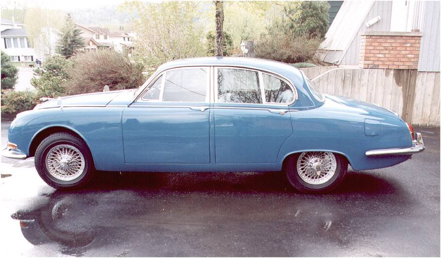
Dave and Diane Symingtons 1966 S-type
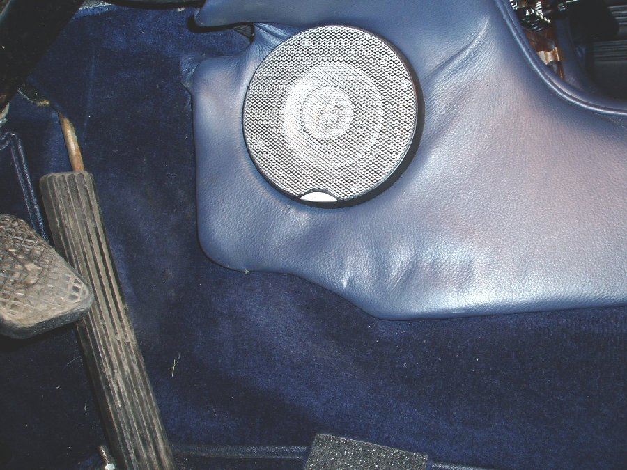
ST-06
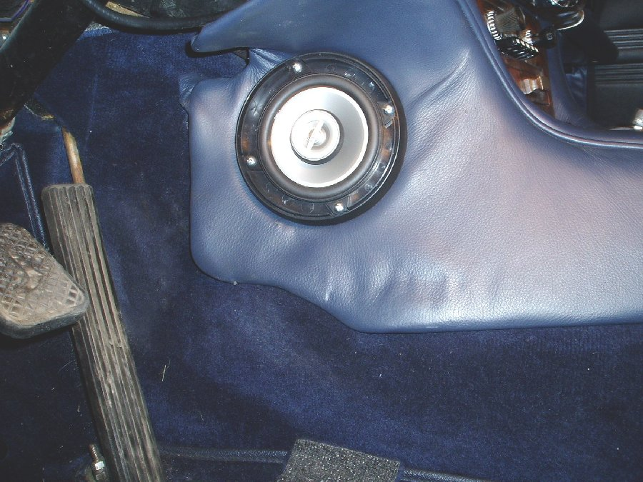
ST-07
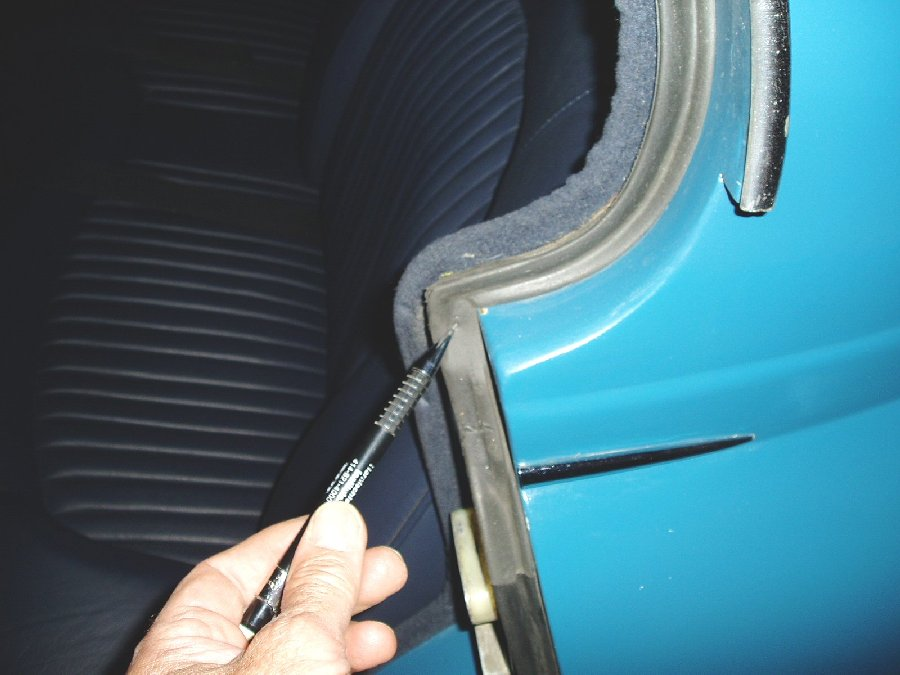
ST-18
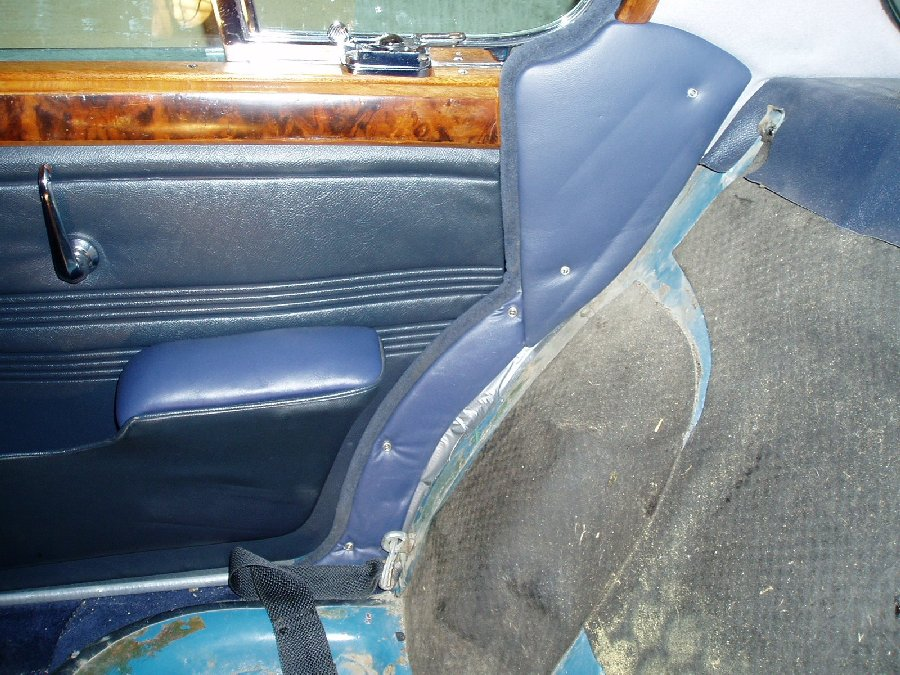
ST-2

ST-19

ST-12
ST-11
ST-13
ST-16
ST-09
ST-10

ST-14
ST-08
ST-17

ST-21
|
New Stereo System in 1966 S Type
Ever since the major part of the restoration was completed on our S-Type Diane and I both knew that
we had to get something done about the radio! The existing “system” was a Blaupunkt AM/FM/SW
radio with only one speaker mounted behind the grille on the drivers side of the centre console.
It had very bad sound!
What we wanted was a good AM/FM receiver, capability to play CD’s and good quality sound with front and rear speakers. One of the main concerns was that whatever system we installed, it had to look like it belonged in the car. Some of the newer receiver units wouldn’t look out of place on the space shuttle and that was not what we wanted. We don’t put our car in shows but we both felt that we had to maintain the original look of the radio. We had converted our car to 12volt NEGATIVE ground earlier so there was no problem with this installation.
We eventually decided to have the radio insides replaced with a modern digital AM/FM while still retaining
the original body and face of the Blaupunkt radio. We wanted a CD changer mounted in the trunk out of
sight. Good front and rear speakers to complement the system was also in order and sufficient power
from the radio so that no additional stereo amplifier would be used if possible. Through the Jag Lovers
resource pages we found Antique Automobile Radio Inc in Palm Harbour Florida,
(www.antiqueautomobileradio.com). We talked with Matt and decided to have him do the conversion of
our radio. They also provided a 10 disk Prestige CD Changer that would work with the new radio. The
speakers we purchased through (www.discountcarstereoplus.com). Specifications for the components
are as follows:
AM/FM receiver:
12 volt negative ground
Digital signal processor.
Original Blaupunkt body and faceplate
Push buttons work for both AM and FM
Tuner knob functions as before
Front to rear fader
Balance control
Treble/bass control
Manual tuning also
4 BTL amplifiers 45watts RMS each built in.
Control wire for switching the power antennae
CD Changer
Audiovox/Prestige 10 CD changer Model SP-11CDP
Hard wired to AM/FM radio
5 - 20,000Hz
Signal to noise 85db
Channel separation 80db
Hard wired controller
Remote wireless controller.
Speakers
Front
Infinity Kappa series 42.5i
4 inch 2way with crossover
50w RMS, 150w peak
sensitivity 90 db
Frequency Response: 75Hz - 21kHz
Rear:
Infinity Kappa series 572.5cf
5 inch by 7 inch 2 way with crossover
100w RMS, 300w peak
Sensitivity 90db
Frequency response 40Hz - 21kHz
Mounting the components:
Before doing anything disconnect the battery!
(Photo ST-01)
Radio:
Pry off the heater control buttons and you’ll see the two mounting screws for the wooden radio faceplate.
Remove these screws and remove radio. Disconnect wires and antennae wire.
The centre console of the Jaguar needs to be removed so this means you need to take out the front seats.
The vacuum lines for control for the heater need to be removed (Best to tag these so they go back
on the correct way)
The hand controls for the heater vents over your feet need to be removed.
The leather covered bump pads on front of parcel shelf will have to be removed.
The heater outlet hose for the rear heat will need removal.
Once the console is removed, remove the original speaker from left side.
The body or frame of the radio did not change so everything will fit back in as it was. There is now a little
extra room in there as the separate 12volt power supply box needed by the Blaupunkt is not required now.
The case of the radio is modified to allow the RCA plugs from the CD device to be attached. We asked
this to be done at the rear of the radio but in retrospect there is actually more space on either side of the
radio chassis so if I were to do this again, this is how I would have asked them to do it.
The power wire was attached to the original wire which is fused with a 14 amp fuse. And is switched with
the ignition.
There is an orange wire for control of the power antennae
There is also a power wire for switching the CD changer on.
There are the eight wires for the four speakers.
All wiring for the radio goes through a multi pin connector making it easy to remove the radio in future
without cutting wires (See problems)
One thing you need to do that is NOT in the instructions is install a good ground wire between the radio
chassis and the SAME ground that is used for the CD player controller. (See problems)
As they say in most of the other stuff I’ve read. . . . Install in reverse order of removal!
Front Speakers:
(Photo ST - 06 and ST -07)
The Infinity Kappa speakers chosen will exactly fit the screw holes from the original speaker grille on the
car. At least on my car they did! I discarded the original speaker grilles as the Infinity speakers came with
grilles that fit perfectly. The installed height of the Kappa speakers are just under 2 inches which is less
than the original so there is a good fit here! Just be careful where you mount the cross-over devices.
There is a good wiring diagram supplied by the speaker manufacturer and the wiring connectors are
different sizes so as not to get positive and negative confused.
As there was no original speaker on the right side you’ll have to make some modifications.
First, the leather behind the right speaker grille will have to be cut and glued back over the console
support material. Cut leather in a star shaped pattern and use some spray headliner or upholstery
adhesive to hold it in place.
Second, the heater control mechanism for switching on and off the rear heat is mounted in the way of
where you’ll mount the right speaker. This control will have to be removed and a longer piece of 2 inch
heater ducting installed. You may be able to fabricate a device to allow keeping the heater control. I
decided to remove it.
Mount the speakers and the in-line crossover on each side of the console. I used machine screws through
the new grille bases and nuts on inside.
Put a little Locktite on the screws to stop the nuts vibrating off and screw everything together.
The new speaker grilles are pushed into the grille bases after the console is installed.
The speaker wires can be connected to the wires and plug supplied with the radio. You need to observe
the correct polarity of each wire and it may be a good idea to make tags depicting location and install
them on each wire.
Note: I will probably install Bass blocker devices on the front speakers in the future as the speakers cant
handle too much Bass and may be damaged if you crank up the volume :-)
Rear Speakers:
The rear parcel shelf has three cut-outs. One large one 14.5" x 4.75" in the centre and two 4.75" square
ones on either side. The Infinity speakers chosen will fit under the square cut-outs with no modifications
to the opening. Mounting holes for the speakers will have to be drilled from below however.
The distance between the rear of the back seat squab and the rear window is only 5.75" at the point where
the rear speakers would be positioned so it would be very hard to install a 6 x 9 speaker in there. This is
why a 5 x 7 configuration was chosen.
Remove the rear seat bottom and back.
Remove the Ambla covered rear parcel shelf material (two screws about 6 inches in from the sides of the
car)
Remove the two leather covered cheek pads on either side of the rear seat squab underneath where the
rear quarterlight windows are located. There are screws coming in from the outside of the car underneath
the rubber weatherstrip material. (Photo ST - 18) Also are two screws that are visible from the inside of
the car. (Photo ST - 02)
Remove the Ambla covered crescent shaped panels underneath the leather cheek pads on each side of
the car.(Lower part of Photo ST - 02) You will be running wiring here.
I chose to mount the speakers underneath the parcel shelf as it required no metal cutting of the speaker
openings. If you choose to surface mount the speakers then you need to enlarge the speaker openings.
This would be quite hard to do from underneath and almost impossible to do from on top without
removing the rear windshield glass. I remember what a pain it was to reinstall the rear window rubber and
chrome strip and don’t want to do that again if I can help it!
Drill speaker mounting holes and mount speakers from underneath. As there is a pronounced lip on
bottom side of the speaker cut-outs in the parcel shelf you will have to find or fabricate a spacer to go
between the speaker and the parcel shelf. This should be about 3/8" to 1/2" thick.
I rescued rear speaker grilles from a 1989 Mercury Tracer that had 5 x 7 speakers and was of the right
blue colour for our Jaguar. On top of these Ford speakers there was a gauze covered spacer that was
exactly 3/8 inch thick that when removed, fit the Kappa speakers perfectly and acted as the required
spacer between the Kappa speakers and the bottom of the parcel shelf. If you check in local auto
wreckers you might find something that will work for your car. The Kappa speakers did not come with
custom grilles but you may find a 5 x 7 speaker from a speaker manufacturer that does.
The square plugs for the speaker cut-outs in the car were removed and discarded. The large rectangular
plug was kept and adapted for mounting the CD Player.
Place the fibreboard covering for the rear parcel shelf back in place loosely and trace the opening of both
speaker cut-outs from the bottom.
Carefully cut out the holes in the fibreboard (sabre saw with fine blade). The foam interliner can be cut out
and removed using a sharp utility knife. The Ambla covering the hole can then be cut in a diagonal fashion
and the material folded and glued to the underside of the fibreboard leaving a smooth opening in the
panel for each speaker.
The speaker grilles (from the 1989 Mercury) have four mounting pins and Pal nuts that need to be
mounted on the fibreboard parcel shelf before the shelf is reinstalled on the car. Careful measuring is
required before drilling any holes. In my case there is less than 1/4" to spare on each side of the
grille.(photo ST - 19) My grilles measure exactly 5.625" x 8.0"
If you feel so inclined you can install some Dynomat sound deadening on the metal surface of the parcel
shelf. However this will make it harder to reinstall the fibreboard cover. I had purchased some Dynomat
but ended up not using it because of concerns over fitting the fibreboard cover back in place.
(Photo ST - 12)
Before you reinstall the fibreboard cover you need to make the mounting arrangements for the CD player
The Kappa speakers for the rear have an adjustable tweeter in the centre of the speaker cone that the
manufacturer says should be angled towards the listener. First thought was to turn those towards the front
of the car. However we angled them backwards with the thought that the high frequencies generated
would bounce off the rear windshield and be reflected forwards. (Photo ST - 11) It seems to work
extremely well. (I’m slightly deaf but I’m sure that a dog or cat sitting in the front seat would be suitably
impressed with the high frequency rendition of the speakers!)
The speakers were bolted in place using the spacers as described above. The Crossovers were
attached and tied to the CD player mounts with nylon tie wraps. (Photo ST - 13)
Wiring to rear of Car:
I installed the speaker wires in left side rocker cavity, DIN cable for CD player in the right side rocker
cavity. Unfortunately because of the unibody construction of the car there is no other suitable way of
stringing wires to the rear of the car. Bummer!
Jaguar had installed a speaker wire for their rear speaker option. It is probably best not to use this and
instead install new speaker wire that matches the power requirement of your speakers. We used 16
gauge paired wire ( in a nice blue colour to match the car). You are going to need about 40 feet of wire.
(I originally bought 30 feet of wire only to find I was about 2 feet too short!!)
The left and right sides of the car have hollow rocker cavities that already carry some of the vehicle wiring.
These cavities can be accessed through a rubber plug in the front face of the rear wheel well. I had
replaced these plugs at time of car rebuild with a small square plate of steel screwed in place and sealed
with caulking (photo ST - 16)
Above these access plugs on the inside of the car and behind the crescent shaped coverings earlier
described is another access hole where the wiring for the rear of the car passes. (Photo ST - 02)
Wiring from both the speakers can be threaded through the grommet between the trunk and the area
behind the side Cheek Covers earlier mentioned, down and through the grommet into the rocker panel
chamber.
At the front of the car remove the Ambla covered kick panel near the dimmer switch on the left side and
the similar one on the right side. (Photo ST - 09) This will expose the wiring going through a grommet into
the rocker chamber and aft to the rear of the car. Remove this grommet. I ended up drilling a new hole
into the rocker cavity next to the existing grommet as it was very tight for the speaker wires and on the
right side of the car, it was impossible to thread the DIN cable through the existing hole.
Jack the car up or put it on a hoist and remove both rear wheels to better access the plugs in the wheel
well.
Next, you will need to find, borrow or make a “Fishing Tool” or borrow an electricians Fish Tape to thread
the wires from the rear of the car to the front through the rocker cavity. I used a fibreglass whip antennae
about 3/8" in diameter and about 10 ft long. Taped the speaker wires to the end with duct tape and
pushed the assembled mess through the hole in the wheel well up to the hole at the front of the car. I had
help from my wife here and after a few tries managed to fish the speaker wires up through the hole behind
the kick board in the front of the car.
Repeat the whole procedure to string the DIN cable for the CD player in the right rocker cavity. On this
side for sure you will have to drill a new hole for this cable on the front of the right rocker cavity as the head
of the DIN cable is too large to fit through the existing grommeted hole. You’ll need about a 3/4" hole
With my wife helping me, and after everything was prepared, the stringing of wires on both sides of the car
took about 40 minutes. Make sure you have enough length of speaker wires at front and rear to finish
making your connections (I didn’t!) then button everything up.
Testing the speaker wires:
Make sure that the wires are connected to the radio correctly. You can test wire continuity with a
Multi-meter, but when you make the final connection to the radio make sure that you are connecting
positive to positive etc. Then connect the wires to the plug supplied with the radio.
Mounting the CD Player.
The CD player came with an assortment of mounting brackets. I selected the ones that would allow the
player to be horizontally positioned and right below the rectangular cut-out in the rear parcel shelf (where
the optional AC unit goes)
I mounted the brackets directly to the cut-out plug with the supplied bolts and reinforced the cut-out plug
with 1/8" aluminium sheeting to make it stiffer.
The cut-out plug was then reattached to the parcel shelf and screwed in place with sheet metal screws to
hold it firmly in place.
The CD player was then attached to the mounting brackets. (Photo ST - 10)
The DIN cable on my unit plugged into the CD player on the drivers side and is the only connection
between the front of the car and the CD player.
I mounted the rear speaker crossovers to the CD mounting brackets with nylon tie wraps. (Photo ST -13)
The CD player came with screws that held the disk transport mechanism stationary during shipping.
These MUST be removed before placing the unit in service. The manufacturer also supplied sticky
decals to cover a few of the mounting holes in the player.
Install any insulating material on the underside of the parcel shelf and your done in the trunk!
CD Changer Control box and Wired Commander Unit
At the front of the car behind the dash or front parcel shelf somewhere you need to mount the small (about
3" by 1.5") control box supplied by Antique Auto Radio that directly connects the CD to the radio. This is
NOT an FM modulator box but a powered device that takes the signals from the DIN cable and converts it
to a signal to the radio via RCA cables. The Wired Commander unit is also plugged into this box and
allows you to control the CD changer manually.
I installed the Wired Commander unit with a Velcro fastener underneath the glove box on the right side
where it is not directly visible from outside or inside the car. The Remote Control for the CD changer
needs to have a direct line-of-sight path to the Wired Commander. (Photo ST - 14 and ST - 08)
There is a control wire from the radio to the CD control box, 2 RCA cables to the radio, the DIN cable to
the CD changer and the DIN connecter to the Wired Commander to be hooked up. There is also a
ground wire. This ground wire MUST be connected to the same ground as the radio chassis. (See
problems)
Power Antennae.
Jaguar had an option for a hand crank antennae for the radio. We installed a regular power antennae in
the same location when we rebuilt the car. It needs a fused power supply and the signal wire from the
radio. (Photo ST - 17)
You’re done!!
Set up the CD changer magazine with some favourite tunes or tune to a FM station, sit back and relax and
listen to your new sound system!
Problems:
1. Initially when the system was powered up it would only produce acceptable sound at very low volumes.
When the volume was turned up there was a rapid popping noise from the speakers. This was eventually
traced to be the need for the radio chassis and CD Control Box requiring a shared common ground.
This was not mentioned in the suppliers information and took quite a time for me to figure out.
2. The multi-pin connector attached to the wiring for the radio had bent pins when it arrived. It took about
30 - 40 minutes to straighten out the pins so that both sides of the plug would connect. I was tempted to
cut the plug off and crimp the wires together but that would cause problems the next time the radio was
removed.
Costs:
Radio Conversion to Digital $399.95
Shipping $29.00
CD Changer $329.95
Shipping $29.00
Infinity Kappa speakers (4) $118.98
Shipping $20.00
Customs and Import Duty $57.05
Speaker wire $20.00
Total $1,003.93 US Funds
Time taken?
You don’t really want to know this as it always seems to take longer than what you think. Especially when
you are designing the system as you go. Once everything was figured out I expect it took me about 20
hours to do everything. Add on about an additional 40 hours for figuring out what type of system we
wanted, how to fit it into the car and finding the used speaker grilles for the rear parcel shelf (they were
free!)
Would I do it again? Yes, most definitely! It is a super sounding system that looks perfectly stock and well
worth the effort.
If anyone else is thinking about doing this I hope that this guide will shorten the time required to do the job,
(Photo ST - 21)
Best wishes,
Dave Symington symingtn@telus.net
1966 S Type 3.8 MOD (with great sound system)
18 - General Information ( Chris Burdo,
June 7, 2005
)
18.1 - Helpful Restoration Tips ( Jeff Warner,
April 29, 1998
)
You must isolate where the fumes are coming from. There are
essentially three areas to look -- Boot , bonnet and underneath.
I have had all 3 so here are a few suggestions.
After you run the car and at a point when it smells the worst,
simply stop and open the boot, stick your head in and take a smell.
If it is a strong odor, then this is where you start. If you do
the same to the bonnet area and it is a strong smell than that is
where you start. You must really get into it at this point to try
to isolate it by where the smell is strongest.
If you do both and you don't get the strong aroma then you need
to check the fuel line that runs from the boot to the bonnet as
well as the tank(s). I just found that my line was broken and it
was pumping petrol into the boot where it was soaked up by the carpet.
Because it was soaked into the carpet, I never found the leak until
recently when I lifted the car and shook the line.
If you suspect the boot area, then what you need to do is simply
turn on the ignition and check for leaks. I had two leaks on my system.
One was where the plastic line went into the tanks (I have 2 tanks on the 420)
and the other was the connectors on the SU pumps. I replaced the plastic
line with metal flare stubs into the tank and I replaced all of the lines
with new rubber in the boot. This seems to have eliminated most of the
smell from the boot. Carefully check where the lines connect onto the SUs.
Sometimes the petrol seeps past the Stainless clamps.
In the bonnet, you will occasionally get a stuck float (or a
Saturated float) which causes the smell. When I had this problem, I took
the carbs off and I used sand paper to clean the rod the float slides on
as well as smoothing the inside hole in the floats. I found that after 35
years the rod had gotten a bit rough and I felt this was not helping the
operation. Also check to see if the arm the float contacts is set properly. If
one of the legs is skewed to the other it will cant the operation and the
petrol will not shut off properly. With the domes and pistons out of the
carbs, you should be able to turn the ignition on, have the pumps pump and
the flow of petrol stop at the level of the jets. If this is not happening
tha this may be your problem
The basic operation is simple: you will only get a smell if the
petrol is exposed to the air. You must go over the entire delivery system
to see where petrol is meeting air in an unauthorized place and manner.
Addition from George Camp, June 14, 2005
Do not forget the 3.8 MKX had an extra area to watch.
There is a valve on the rear bulkhead to prevent drain back from one
pump to the other.
I am actually referring to the ''Non-return valve in the
Rear bulkhead. If you look at J32 (parts manual) p 279 item 33 you
will see what I mean. The later external pumps had built in non-
return valves so the part was eliminated but the Lucas E-2FP had no
such valve and indeed the first external pumps also had none. Without
the valve they would transfer fuel to the unused tank. I do not
have time to look it up but there was a tech. or parts bulletin
that covered the change. The point of my post is this valve is
often overlooked and is prone to leaking in its aged condition.
Paul Scott adds on June 17th, 2005:
I would like to add the following possibilities, although I
am not sure if they all will relate to the Mk10:
Banjo fittings on the carbs and fuel pump can weep, they may
need re-flattening (lapping on emery on a mirror), I have
never really been able to get the fiber O rings on these
banjo fittings to seal properly and have had to resort to
adding fuel proof gasket sealer. On the 340 and Mk2’s the
fuel filler cap should not be vented, the tank is vented
through an overflow pipe that comes out of the side of the
filler pipe and is vented out under the car, clipped to the
bottom of the petrol tank. If the cap is vented then the
fumes can find their way into the boot. The Auxiliary
Enrichment Carburetor (automatic choke) is open to the air,
the fuel level is the same as the level in the float chamber
and the petrol sits in the bottom of the air intake.
I converted to manual choke as on the E-types, which has
vastly improved but not eradicated my fume problem, starts
from cold much better though.
18.2 - To Modify of Not, That is the Question! ( Jon Garde,
)
The XK engine has a cast aluminum head with hardened steel valve seats pressed in. Valve seat erosion, which occasionally occurs in older American engines, is the result of the valve welding itself to the valve seat in the absence of lubricating lead, and taking a small chunk of the seat when the valve opens. In these engines, the valve seats were machined directly into the soft cast-iron of the head, and relied on lead additives to provide lubrication for longevity. The original valve seats installed by Jaguar are hard enough to withstand this abuse, and will give years of service.
18.3 - Jaguar Diseases ( George Haynes,
)
One characteristic of switches that most people are not aware of
is that they require a certain amount of current to work properly.
Under normal circumstances a certain amount of oxidation will build
up on the switch contacts which has the effect of insulating the
contacts from each other.
Packing the switch with dielectric grease and designing the
contacts so they wipe each other helps solve the problem, as
does wetting the contacts with mercury. However, none of these
design techniques are present in the SU fuel pump. It needs to
rely on current flow to burn through the oxide layer.
If you put a transistor in the circuit you eliminate the current
flow through the points so they don't burn and wear out but this
creates the aforementioned second problem instead.
The points in the SU fuel pump are perfectly capable of handling
the 3 Amps that the pump draws, but they get burned by the high
voltage arc that is generated when the points open (just like an
ignition circuit).
The solution is simply to install a suitably sized (3 Amp) diode
across the coil. Such diodes are available from Radio Shack as part
numbers 276-1141 through 276-1144. Diodes are polarity sensitive,
so connect the diode lead that is marked with a band to the coil
terminal that connects to the positive side of the battery. Forget
the transistor and just use the points to carry the current.
There's no need for the capacitor if you have the diode.
In spite of the fact that I love to add electronic devices to our cars,
this is the best solution for this application.
18.3.1 - More Jaguar Diseases ( Pater Havas,
)
After reading your column on Jaguar Diseases, I felt compelled to share the results of my own research in this area with your readers. While the field is certainly broad,a nd there is no lack of subjects to study, I feel it is imperative to classify the various afflictions, infections, syndromes, and behavioural traits before new models come out and corrupt my research. Below are a few of my most recent findings. I welcome all comments from like minded field researchers.
Spontaneous Part Regeneration SPR:
The innate ability of any Jaguar part, when dismantled from the car after failure
and replacement, to "heal" itself and be suitable for service again if left in a closed dark place for long enough, or immediately upon the part no longer being available either rebuilt of NOS from any source.
Indications:
A) Immaculate diaphragm healing.
B) Spring height re-establishment.
C) Piston Ovality suddenly acceptable
D) The inclusion of the phrase "Close enough" in your vocabulary.
E) A .22 feeler gauge appears thin.
F) Sand blasted Pot metal parts look almost as good as new
G) The sure and certain hope that "Maybe THIS time it won't break" becomes dogma.
H) A loss of memory for exactly how many miles the part already had on it, but the conviction that it "wasn't much".
Scroungers Scourge:
This affliction usually occurs early in the restoration, in what Psychological experts have come to call the "Collection" phase. It is typified by the patient scouring auto-jumbles, and junk yards for ANY period parts and / or accessories. Said material is then acquired, and although it has no use whatever in the restoration of the car at hand, is trotted out at the merest suggestion of the drop of a hat with the wry comment that "You've never seen one of these." or "I know lots of people who would kill to have some of these.". After appropriate billing and cooing over the object(s), the patients status has risen immensely, and the material is then re-shelved to await the next victim. There is no known cure. Early stages of this affliction are characterized by people commenting that they 've " .got two of those back home in the barn." when shown a particularly desirable piece at an auto-jumble.
Occularmetrinchosis:
The developed ability to instantly tell which nuts and bolts on a Jaguar are metric, which are not, and which wrenches can be cross-referenced to round the shoulders of both. Often mis-diagnosed as Hexasnapophobia, or fear of reading wrench sizes and frequently confused with rank stupidity, the afflicted person can often be heard mumbling: " I don't get it. It worked on MY car"
Biomechanical Bonding:
Dismissed by some as a myth, researchers are increasingly convinced of the existence of this strange phenomenon, which to date apparently is prevalent only with British made Automotive paraphernalia. Symptoms include a close attention to detail when re-building a particular part with the factory approved kit, and complete instructions.
The most severe evidence is with Lucas Generators , S.U. and Stromberg Carburettors. When correctly assembled and installed with precision, the part will have so bonded with it's maker, that it will steadfastly refuse to function on it's own, and "Just want to be taken apart again". There can, therefore, be no substitute for slap-dash assembly.
Double Optipupilotomytosis, or "Bush Babies Syndrome":
A condition caused by driving Jaguars at night, relying on Lucas to show you where your dash-board is. The victim's pupils often expand to ten times their normal size, requiring them sometimes to wear sun-glasses at night when arriving at their destination. Sufferers often prefer the company of their own, to avoid the possibility of being suddenly blinded by lighted cigarettes, flash cameras or inadvertently stepping in front of a BMW.
Sportsmans Crook-neck:
A painful and embarrassing physical condition, caused by Jaguar drivers cocking their heads back, while leaning forward, to actually see the end of the front wing when pulling out of a parking space. Sufferers are frequently confused with erudite snobs, due to the "Nose in the air" stance they assume in public. The experienced Jaguar driver, however, will instantly recognize this for the debilitating condition that it is, and take pity on the afflicted.
Retrovisionary Trauma:
A syndrome shared with Sail-boat owners. The disease is typified by an inability to remember anything about past Jaguar ownership, except through a rose-colored fog.
Merlin Syndrom
The conviction that normal physical laws do not apply to common consumable parts on Jaguars.
They wear out due to:
A) Anger
B) Fatigue
C) Somebody else's incompetence
D) Magic.
Fahrvernugen:
The inability to recognize that common consumable parts on Jaguars do not wear out due to:
A) Anger
B) Fatigue
C) Someone else's incompetence
D) Magic.
18.4 - Racing the Big Saloons ( Larry Martz,
)
Yes, it is standard practice to do the brake seals etc while subframe is removed, and set-up the handbrake properly. Use coppa ease on handbrake pivots etc. Set-up handbrake before adjusting cable., but we are away ahead here :-)
For removal of subframe, I found a (long) piece of 4*2 to push through the subframe as it is lowered, and lever the rear down, to stop it from tipping forward. It is very front heavy.
1st remove grease nipples from bottom of hub-carrier, otherwise they will get broken off! Note shims between diff and drivehshaft, this is your wheel camber. There are shims at inner end of lower arm, shims for bearing set-up on the wheel bearings and on the lower fulcrum on the hub carrier.
Take your diff to a shop to be done, it probably isn't worth the time (unless it is OK of course).
All the other parts (and I mean every bearing and seal), UJs, arm bearings etc are cheap, and worth replacing. A good rear end makes the car very driveable :-) Some UJ's have grease nipples, some don't.
The most difficult is the wheel bearings, The removal of inner race of the outer bearing on the hub (as opposed to aluminium hub carrier), is a b*****d whether steel or whire wheel hub, and may need shop help, depending on what you have access to. I have known it fall off, which probably means the hub is useless. everything else can be drifted, I used a hydraulic press.
On setting up, you must understand how the end float of the hub bearings works, you do not need the special tool referred to, it is just a spacer of an exact dimension (50 thou), you can use any spacer as long as you measure it. You cannot tighten the rear hub bearings just by doing up the big nut tighter. The endfloat is governed by a spacer and shims. Don't believe anyone who tells you otherwise. The book says shims are obtainable in 3thou sizes, but I have seen them in 2 thou sizes
The preload (as opposed to float) on the hub-carrier lower bearing shaft. When you drift out the lower shaft, use a dummy shaft. If you dont, there are thin shims in there in the centre, which will get dislodged otherwise, and then mangled as you push a shaft through. The taper bearings in here often have dried up with rust, as the seals can be poor, and the water gets in. Also, the bearings only revolve by a few degrees by comparison to normal bearings.
If you are buying in kit form of parts, beware there are two sizes of outer oil seals for the bearings, changeover 1B5166, 1B25707, 1B55701, 1B78500 depedning on 3.4/3.8/LHD/RHD.
Shock absorbers/springs can be done any time, and the set-up is really a personal preference.
18.5 - Genevieve: A Love Story, MKIX Book ( Kon Kakanis,
March 24, 2003
)
The late Larry Martz put me onto a book called "Genevieve - A Love Story"
several years ago. It was a self published book relating the story of a Mk
IX bought new, sold years later, and then re-purchased and restored.
I found my copy by registering on a few bookshop sites under 'Wanted'.
Since then, a notice arrives a couple of times a year telling me it is
available again.
18.6 - Differences of a MKX to a 420G ( Robert Meyer,
December 26, 2002
)
Long time ago, maybe in the beginning of December 2002
Andy wrote: >> Mk X vs 420 <<
Can someone(s) please expound upon the differences
between the Mark X and the 420?
They seem to be extremely similar, yet the 420 seems
to be higher priced/more sought after.
Andy Litkowiak
Hi Andy, my answer seemed to be rejected automatically
as I made some faults. So I try again:
To distinguish between Mark X /420G and 420 seems to be
a problem even for automobile journalists and some
Jaguar book writers.
The outside distinctive features between Mark X and 420
are visible even from a distance of several meters.
First you should distinguish between 420 vs 420G.
The much bigger 420G ("BIG GEE") really had only few
exterior differences to the Mark X, as the "BIG TEN"
was its direct predecessor and for a first view had
not more than a new name.
So a mixing up of Mark 10 vs 420G would not be such
a big fault.
There were only few changes with the 420G:
Additional chrome lining on the sides
with small signal lamps on front end,
grille with stronger middle bar,
smaller lamp glasses, new wheel caps as well as
two tone colour as desired. That was all from outside.
Interior and technical changes were some more:
Upholstered dashbord top with central clock
and new technical details will learn from my "BIG JAG -bible":
JAGUAR Mark VII to 420G
THE COMPLETE COMPANION
Author: Nigel Thorley
Bay View Books Ltd, Bideford, Devon, GB
ISBN 1-870979-41-9
The first Mark X series had a 3.8ltr engine,
followed by the second with 4.2litre engine.
The third series, the 420G had a 4.2litre engine like
series two, but a new name.
To distinguish between 420 and 420G you first should know,
that the 420 was a noticeable smaller car.
To make it simple - imagine a 2step evolution of the Mark 2.
First step: Give it a new back end looking like a Mark 10 boot
and you'll get an S-Type.
Second step: Give it a front end looking like Mark 10/420G
and you will get a smaller brother of a Mark 10/420G,
named Jaguar 420.
Distinctive features visible from outside:
- 420 had rectangular horn grilles instead of round ones,
- 420 showing B-column, not visible at Mk10/420G,
- 420 opening only motor hood, Mk10/420G opening complete
front with grille (comparable with XKE).
|