|
- ( ,
)
1 - Introduction ( Paul Stow,
December 1, 2001
)
The X300 was introduced in 1995, as the latest in a distinguished line of cars branded the Jaguar XJ6. In addition to the base model, Sovereign, Vanden Plas and Daimler models were made available in varying markets and with increasing levels of trim and equipment. The car was available with 3.2l or 4.0l engines and, in the top of the range XJR model, a 4.0 supercharged variant.
Jaguar had enjoyed increasing success with the previous XJ40 model, which since it’s introduction in 1987 had undergone a number of updates and continuously increasing production and quality. The X300 was to build on this success, and formed the platform with which Jaguar re-emerged as a leader in reliability and customer satisfaction, forcing rivals from Germany and Japan to sit up and take notice.
To many people, the curves of the X300 body shape were reminiscent of earlier XJ6 models as opposed to the more square lines of the XJ40. The overall proportions are similar, however, with the elegant lines matched by limited rear legroom and a shallow boot caused by locating the spare wheel and battery under it's floor.
The interior of the X300 is immediately familiar to XJ40 lovers, with the central 'ski-slope', J-gate transmission selector, and 6 gauge instrument binnacle. Closer examination, however, shows many detail improvements to stereo and air conditioning systems, revised panelling, door seals etc etc.
Under the bonnet, the basic layout is again familiar with the AJ16 engine being the last in a long line of six cylinder, double overhead cam, 24 valve engines from Jaguar, stretching back to the Le Mans winning C-types of the 50’s. Like the interiors, however, the AJ16 contains a host of detail improvements, the most visible of which is the replacement of conventional coil and distributor ignition by an individual coil on plug arrangement, eliminating the need for HT leads.
For the first time on a modern Jaguar, the XJR model added an Eaton type supercharger to the 4.0l engine, increasing power to 316bhp - more than available from the 6.0l V12. To handle this power, the XJR shared the GM gearbox with the V12, had stiffened suspension to provide a sportier feel to the car,and a distinguishing mesh style front grill.
1.1 - VIN Numbers and Year of Manufacture ( Paul Stow,
December 1, 2001
)
1995MY From 720125
1995.5 From 739427
1995.75 From 746613
1995.75 LWB From 746814
1996MY From754304
1997MY From 787954 to 812255
1.2 - About the Guide ( Paul Stow,
December 10, 2001
)
This guide is based on a '95 UK Spec XJR, and so details will differ from differently specified models. In particular, other engine specifications will not have the supercharger and intercooler, and US spec models will have additional emissions equipment such as EGR ( Exhaust Gas Recirculation ).
Some of the less common tasks are omitted, on the basis that the author and list have no experience of them yet! This also hopefully means that the vast majority of X300 owners won’t need to know about them either. However, if you think something should be included then please let us know.
10 - Bodywork and Interior ( ,
)
The X300 bodywork and underbody are generally free from rust and other vices. The interior is also well put together and not prone to rattles and squeaks. To maintain this condition, care should be taken to ensure cable runs and fittings are correctly reinstalled and any tie-wraps or other fixings replaced before reassembly is completed.
10.1 - Access to Centre-Console - Ski-Slope Removal ( ,
)

|
Open the ashtray, remove the lighter and internal bin and undo the two screws at the rear. Remove the ashtray itself, disconnecting the electrical connection to the lighter as you do so.
Feel into the hole and forward under the centre wooden trim. There are two nylon wing-nuts, upside-down, holding the wood in position. Undo them.
Remove the plastic transmission selector surround by squeezing gently on the sides to release the clip fixings - two on each side. Lift the plastic and disconnect the Sport/Normal switch wiring.
Remove the chrome / leather selector surround, again by squeezing gently. This time the fixings are at the front left, front right and rear middle of the surround and it is often best to start with the one at the rear. It can be a little tricky and frustrating, but it will finally release so try not to force it.
From the back, ease the main wooden trim panel upward so that the bolts clear their mountings and then withdraw it backwards and away.
You can now access the climate control unit, clock and radio units. Removal is simply a matter of undoing the six fixing screws and pulling the unit forward. Take care not to stretch or force any wiring. Refiting is equally simple, but take care not to trap wires or loosen any other connectors.
10.2 - Doors ( ,
)
10.2.1 - Loose Wing Mirrors ( ,
)
Gently prise off the plastic cover on the bottom of the hinge and use a long Philips head screwdriver to tighten the three screws. If the problem reoccurs, try Loctite or something similar to hold the screws tight, or alternatively fit a slightly fatter screw.
10.2.2 - Changing the electronic window/mirror control ( Olly,
June 11, 2005
)
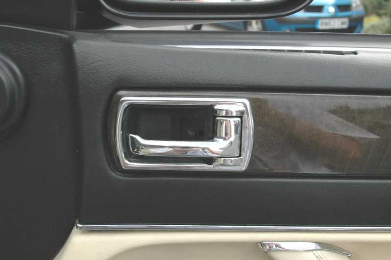
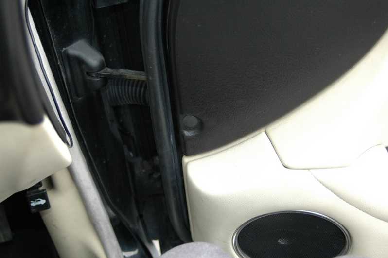
Starting out is relatively simple...using the flatheaded screwdriver, remove the plate behind the door opener.
Remove the screw there, and the plastic behind of the doorhandle should come out with relative ease!
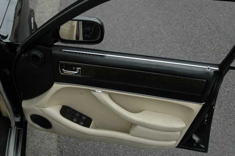
Press on the wooden panel and slide it towards the steering wheel, it should then leaver out without too much fuss.

With the wooden panel off, there should be two screws behind that (sorry, no picture!), remove these and the top half of the door should become loose. Pull this up at the lock end (and make sure the m

With the top half of the door pulled back, you should be able to get at the top screw that holds the door panel on.
Next, remove the red light cover at the bottom of the door (pulls downward), and remove the small flat-headed screw (note, may be a philips!)
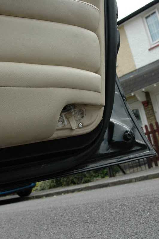
The door assembly should be fairly loose by now, the final part is to remove the black lug found on the inside of the door near the hinges. With that removed, gently pull the leather assembly backward
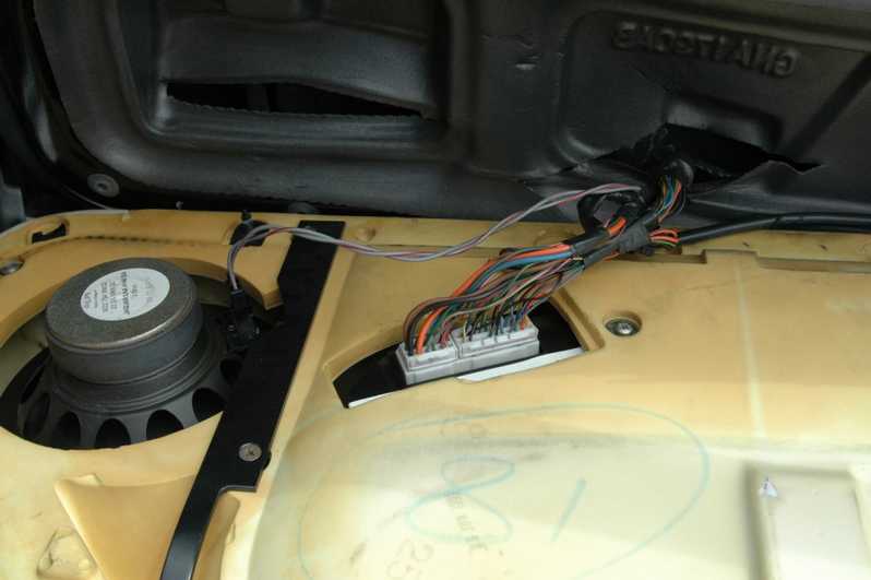
The door assembly should be fairly loose by now, the final part is to remove the black lug found on the inside of the door near the hinges.
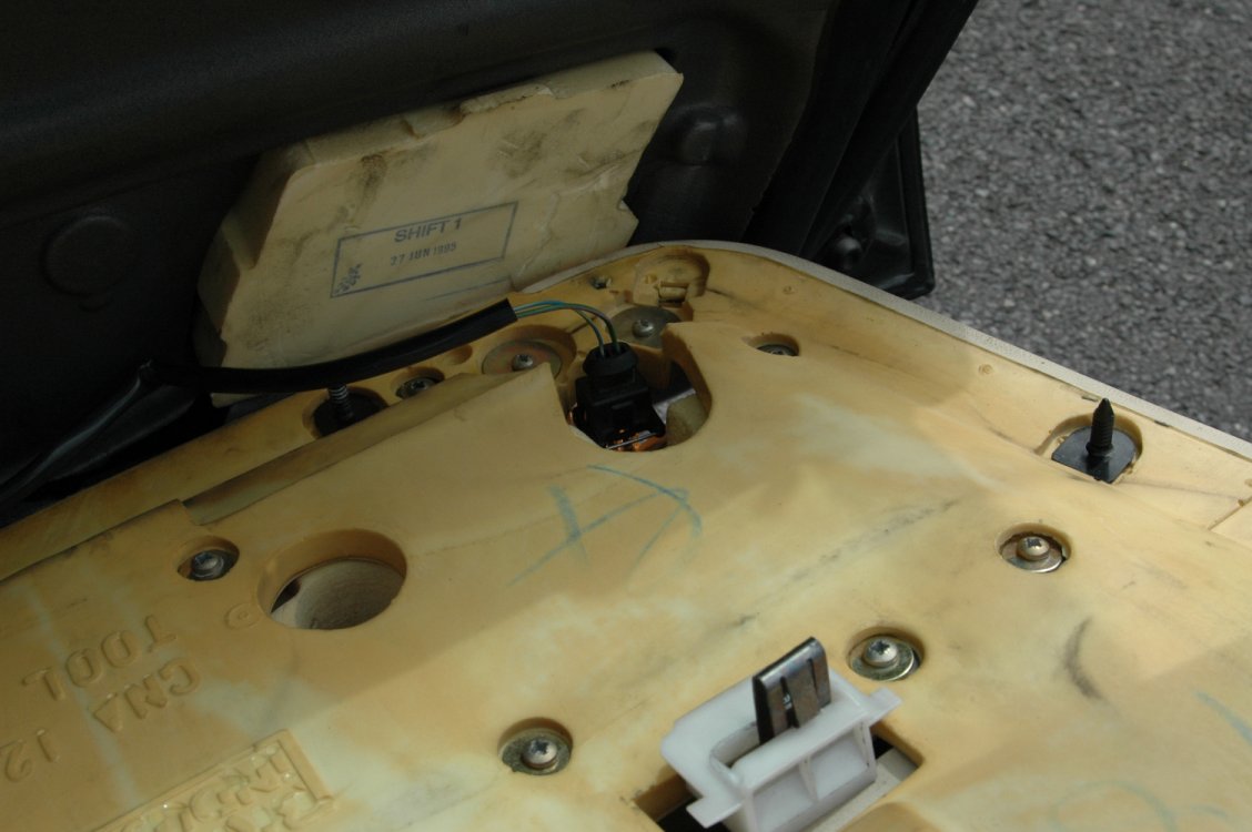
Finally, you should have the door assembly clear now.
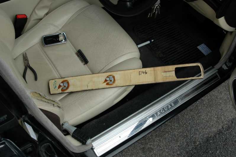
Flip it over & remove the bar on the back (note, make sure you put this back on during re-assembly, or else you ll have to go through all the above again :)
|
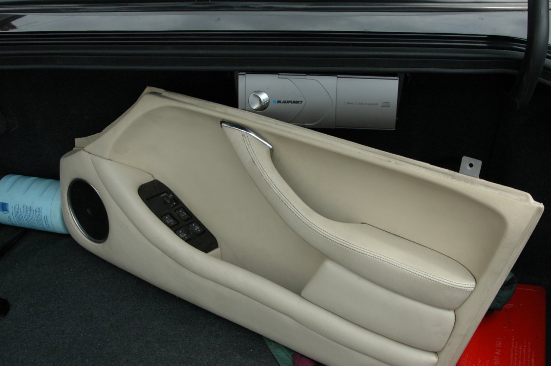
If like mine, your electric window control unit has lost the little joystick that lets you adjust the mirrors, changing it is actually a lot simpler than it looks. Tools needed are a flatheaded screwdriver, a decent sized phillips screwdriver and a pair of pliers (although, this could probably be swapped for a ratchet bit of the appropriate size - will check & find out what size it needs to be!).
I picked my replacement unit up from JoJags for a very reasonable Ł60+vat (worked out at about Ł75 after vat & postage), they were great...I ordered it on Thursday, and it was here on Friday morning!
I'd also recommend picking up a couple of spare clips which hold the leather half of the door onto the frame, as two of mine were broken in the process (will add the Jaguar part# when I get round to picking a couple up!)
One final note, I'm not a mechanic/professional at this, although this is really as far as I'd want to go with fiddling with my Jag...if at any point, you're not happy or something doesn't seem right, stop & get someone who is a professional...it'll be a lot cheaper than the alternative :)
10.4 - Keys ( ,
)
Like the XJ40, the X300 uses Tibbe style keys. If the master key is lost, these can be cut from a code which can be derived from an existing key.
The lock has 8 tumbers, and for each tumbler the key has either no cut ( code 1 ) , a half cut ( code 2 ) or a full depth cut ( code 3 ). The eight digit code is simply a digit per tumbler, reading from the body of the key towards the tip.
10.5 - Rear Fuse Box Access and Seat Removal ( ,
)
Set in the rear floor carpet, just ahead of the seat leather, are two screws which allow the vertical panels at the front of the seat base to be removed. This gives access to the left and right rear fuse boxes and relays.
There are then two more screws holding the rear seat cushion. Push the seat belt buckles down through the hole they come out of, before then lifting the cushion.
The seat back is held in place by two screws in the middle and two at the edges, visible where the cushion used to be. To remove the back, first lift upwards and then pull out.
10.6 - Access to Boot / Trunk ( ,
)
If the locking mechanism fails or no power is available, it is possible to open the boot using a long thin screwdriver through the lower right licence plate mounting hole.
Follow the linkage rod from the lock mechanism itself going left, towards the centre, to where it joins the catch mechanism and push here. It can help to shine a light through the left side licence plate hole, and also to get a second screwdriver in here to take a little of the tension off the catch itself, though not too much or it will spring back into place.
10.9 - Body Rust ( ,
)
Some vehicles have shown evidence of rust around the windscreen seals, on the A-pillar and around the sunroof. Whilst not serious, quick treatment will help avoid later problems.
11 - Electrical ( ,
)
11.1 - Fuses and Relays ( ,
)
Fuses are contained in 5 main fuse boxes as listed below. The descriptions are from the Jaguar handbook and aren’t always the clearest. When diagnosing a problem, bear in mind that several fuses may be involve in getting a particular component to function ( eg power feed, control relay feed, electronic control module feed ), so do check the full list.
Engine Bay Left |
|
|
F1 |
25 |
Heated Front Screen
– Right Side |
F2 |
10 |
Main beam headlamp
– Left side |
F3 |
25 |
Starter Solenoid |
F4 |
10 |
Dip beam headlamp
– Left side |
F5 |
10 |
Side light, indicator
and repeater – Left side |
F6 |
20 |
Windscreen wiper |
F7 |
|
Unused |
F8 |
15 |
Air conditioning
water pump |
F9 |
|
Unused |
F10 |
10 |
Horn 1 |
F11 |
30 |
Engine Cooling fans
– series & parallel modes |
F12 |
|
Unused |
F13 |
|
Unused |
F14 |
10 |
Horn 2 |
F15 |
25 |
Heated Front Screen
– Left Side |
F16 |
|
Unused |
F17 |
30 |
Engine Cooling fans
– series mode |
F18 |
10 |
Front Fog lamp –
Left side |
|
|
|
Engine Bay Right |
|
|
F1 |
|
Unused |
F2 |
10 |
Main beam headlamp
– Right side |
F3 |
|
Unused |
F4 |
10 |
Dip beam headlamp
– Right side |
F5 |
10 |
Side light, indicator
and repeater – Right side |
F6 |
5 |
Engine ECU |
F7 |
25 |
Air pump ( 6 cyl
) Ignition coils ( 12 cyl ) |
F8 |
10 |
Air con clutch (
note separate inline fuse ) |
F9 |
|
Unused |
F10 |
5 |
Alternator, Lighting
control module – Right side, Air con clutch, windscreen &
headlamp wash heaters |
F11 |
20 |
Engine ECU relay
supply, injectors |
F12 |
10 |
Engine ECU, Starter
Relay, ignition coil sensing and air pump ( 6 cyl ), injection
relay and ECU sensors ( 12 cyl ) |
F13 |
10 |
Windscreen washer
pump |
F14 |
10 |
Oxy sensor heaters,
idle speed control valve |
F15 |
|
Unused |
F16 |
10 |
Air pump control,
Vacuum valve ( 12 cyl ), intercooler water pump ( 6 cyl supercharged
) |
F17 |
30 |
Headlamp power wash
pup |
F18 |
10 |
Front fog lamp –
Right side |
|
|
|
Rear Seat Heelboard
– Left Side |
|
|
F1 |
|
Unused |
F2 |
10 |
Heated Door Mirrors,
Instrument Illumination |
F3 |
15 |
Seat motors –
Right side |
F4 |
15 |
Seat motors –
Right side |
F5 |
10 |
Instruments |
F6 |
5 |
Seat ECM, low power
door switches, mirror motors |
F7 |
30 |
ABS pump |
F8 |
|
Unused |
F9 |
20 |
Cigar lighters |
F10 |
5 |
Cruise control |
F11 |
20 |
Heater blower –
left side |
F12 |
5 |
Instruments |
F13 |
15 |
Steering Column
motors |
F14 |
10 |
Auto transmission
ignition switched supply |
F15 |
30 |
Window motors –
left side |
F16 |
5 |
ABS ignition switched
supply |
F17 |
|
Unused |
F18 |
10 |
Air Con supply |
|
|
|
Rear Seat Heelboard
– Right Side |
|
|
F1 |
15 |
Central Locking |
F2 |
5 |
Gearshift interlock,
Centre console switches, interior lighting switch |
F3 |
15 |
Seat motors –
left side |
F4 |
15 |
Seat motors –
left side |
F5 |
5 |
Auto transmission
ECU |
F6 |
|
Unused |
F7 |
30 |
ABS Control |
F8 |
10 |
Interior lights,
boot lights |
F9 |
25 |
Seat heaters |
F10 |
5 |
Diagnostic system,
Fuel pump relay coil |
F11 |
20 |
Heater blower –
Right side |
F12 |
10 |
Air con, Seat ECM,
Mirror heater relay, Power steering |
F13 |
|
Unused |
F14 |
10 |
Mirrors, heater
rear window, cigar lighter, rear lighting control |
F15 |
30 |
Windows – Right
side |
F16 |
10 |
Windscreen wipers,
Front screen heater control, Front lighting control – left
side, water pump relay, headlamp levelling, clock |
F17 |
15 |
Airbag |
F18 |
15 |
Sunroof |
|
|
|
Battery Compartment |
|
|
F1 |
25 |
Stereo |
F2 |
5 |
Tail and plate lights
– left side |
F3 |
15 |
Reverse lights,
stop and indicator light – left side |
F4 |
10 |
Security system |
F5 |
10 |
Main CPU |
F6 |
5 |
Diagnostic system,
phone |
F7 |
30 |
Fuel pump |
F8 |
15 |
Boot release, aerial,
stereo unswitched feed |
F9 |
15 |
Rear fog lights,
stop and indicator light – right side |
F10 |
5 |
Stereo control relay |
F11 |
25 |
Towing module |
F12 |
5 |
Phone and accessory
relay |
F13 |
10 |
Accessories |
F14 |
|
Unused |
F15 |
25 |
Heated rear window |
F16 |
5 |
Airbag warning |
F17 |
|
Unused |
F18 |
5 |
Tail and plate light
– right side |
|
|
|
11.10 - Sound System ( ,
)
11.10.1 - Radio Wiring ( ,
)
The purple/orange wire in the radio wiring harness will mute the radio when grounded. It can be directly connected to the yellow wire of a Nokia car kit for automatic mute when the phone is in use.
11.10.2 - Radio Aerial/Antenna Replacement ( ,
)
These seem to be a commonly failing item. The wiring connector was changed during the lifetime of the car, so ensure you get the right one when replacing.
When replacing, lift it slightly up at the bottom and then slide it down over the window button.
11.10.3 - Radio Aerial/Antenna Maintenance ( ,
)
Periodically wipe the raised antenna with a damp cloth in an upward direction, which avoids pushing dirt into the mechanism. Switch-cleaner is preferable to WD40 as a cleaning agent, as it does not leave a sticky residue behind.
The standard radio unit will periodically display a message requesting that the aerial mast or cassette unit be cleaned. This is a useful reminder, but more frequent cleaning, particularly in dirty road and weather conditions, may be advisable.
11.10.4 - Radio Connections, CD Player and Cartridge Removal ( ,
)
The standard radio has an 8 pin DIN style socket for attaching the CD stacker, which is wired through into the boot. Where no factory CD player is fitted, the Alpine CHM620 can be fitted using the existing wiring and will be controlled from the standard head unit.
The stereo also has a 5 pin DIN socket for connecting a separate power amplifier, available in some markets to drive a sub-woofer.
In addition, there is the main 20 pin connector to the stereo, with pins 1 - 10 on top going right to left and pins 11 - 20 on the bottom. 1 and 10 are 12V feeds, 4 switches the lighting on and off and 3 is a variable feed from the lighting dimmer circuit.
If the CD cartridge appears to be stuck, try pushing a credit card or similar under the cartridge to the right of the eject button.
11.11 - LCD Clock ( ,
)
Clock modules occasionally suffer from faint displays, caused by bad contacts between a circuit board and flexible ribbon cable inside the unit. It is possible to make a repair, though some may consider it to be a less than professional fix!
Access can be gained following the instructions in section 10.1. Remove the connector at the rear of the clock unit itself, undo the four screws attaching it to the rest of the assembly and then take it to a bench area for further work.
The unit itself is opened by undoing the small screws at the rear and releasing the plastic tabs. Whilst the unit is open, take care not to lose any of the small components in there. Release the LCD panel itself by carefully spreading the black tabs holding it into the white plastic bracket. The panel is attached to the main circuit board by a ribbon cable, and it is the connection at the circuit board end that is the problem.
Tape the ribbon cable in place and use a business card or piece of pizza box ( both have been successfully deployed! ) to put pressure on the ribbon cable where it connects to the pcb, behind the white plastic bracket.
Take the unit to the car in plug it in. Use the time set buttons to cycle through all the digits to make sure the fix is complete before reassembly. If segments are still missing or faint, additional pressure may be needed on the ribbon cable.
When all is working, reassemble the clock unit and then refit into the centre console. Attach the cable and take care not to stress any other wires as you fit the console back into position.
11.12 - Memory Seats and Steering Wheel ( ,
)
Some models are fitted with the memory seat, steering wheel and mirrors functionality. The ECU's associate the position of the various devices with a particular key fob and adjust them accordingly.
The motors, particularly for the steering wheel, are known to fail and replacement has been the only solution reported. In some cases, the system appears to become inactive, which can be overcome by disconnecting the battery for an hour or so.
11.13 - External Temperature Sensors ( ,
)
These are located in the brake cooling ducts, behind the front bumper and in front of the wheelarch liner. Access can be obtained by removing the front undertray.
The left hand sensor is used as input to the climate control system. The right hand sensor is used to control the washer reservoir heater and washer jet heaters, active below 4C, and to control the heated seats, active below 26C.
11.14 - High Level Brakelight ( ,
)
Where fitted, this is driven from the relay located in the red, right hand socket in the boot fuse box. The relay is identical to the two others adjacent.
11.15 - Front Indicator Bulb Replacement ( ,
)
The manual indicates a special tool is required to remove the indicator unit from the front bumper. The tool is flat plastic blade, and can therefore be improvised yourself. You can use metal if you are careful to protect the finish on the bumper.
The blade slots into a gap on the inboard side of the indicator unit and releases an internal catch by pushing it to the outboard side of the car.
Bulb replacement and refitting the unit and then straightforward.
11.16 - Sports / Normal Switch Light Replacement ( ,
)
|
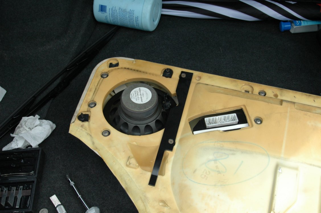
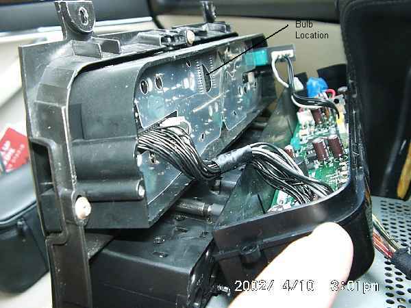
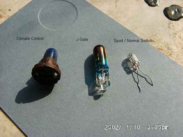
Jaguar does not offer a replacement bulb, but insists you replace the switch. However, replacement is straightforward with a sub-miniature bulb as sold in electronics shops.
To gain access to the switch, remove the ashtray and plastic transmission selector surround (see section 10.1 of this guide).
Using a small screwdriver, release the clear plastic lugs holding the lower part of the switch into the black upper casing and remove the lower part of the switch. The bulb sits inside a small piece of rubber which itself sits on two metal prongs which carry the current to the bulb. The wires from the bulb go back up through the rubber in the same holes as the mounting prongs.
Remove the blue cap from the bulb then pull the rubber mount off the prongs. Gently pull the bulb wires through to the lower side of the rubber, straighten them, then lift the bulb out of the rubber from the top.
To refit, put the new bulb in, making sure the wires go through the two tiny holes in the rubber mount underneath the bulb. Bend the wire round and up inside the mounting holes, then push the rubber back down onto the prongs. Make sure the switch position is the same on upper and lower halves of the switch, then click the lower assembly into the upper casing.
Reattached the wiring and refit the plastic transmission surround and ashtray.
11.2 - Headlight Removal ( ,
)
The headlights are mounted on three ball joints and can be removed by pulling the whole unit firmly. They are sealed beam units and must therefore be replaced as an entire unit should the glass be broken
11.3 - Climate Control Test and Diagnosis ( ,
)
The climate control system is significantly different from earlier XJ40 models in that all flaps and valves are electrically operated, with no reliance on engine vacuum. The system is of the 'constant air flow' type, meaning that fan speed is adjusted based on road speed to maintain the desired flow rate.
The system can be put through a self-test procedure as follows:
Warm the engine then switch off. Press both 'Auto' and 'Recirc' buttons and hold whilst restarting the engine.
All the panel LED's and LCD display will flash. Any areas failing to flash suggest a problem with the bulb, display or function in that area.
Press 'Auto'. If the display is zero, then no error codes are stored. Any other number is an error code. Use 'demist' to cycle through up to five stored codes. Press 'demist' and 'heated rear window' to clear a displayed code. Code 23 indicates low refrigerant pressure.
Press 'Recirc' to enter diagnostic mode. Repeatedly pressing 'Face' will step through the 8 different combinations of vent actuation and you will be able to hear and feel vents and fan operating.
Pressing 'Off' will restore the unit to normal operation with the default settings.
List of control codes:
0 - Normal Operation - No fault codes present, wait 30 seconds for system
self-check.
11 - Motorized In-car Aspirator (sensor element)Open / short circuit. Panel
fault codes are not stored for blown aspirator failure of motor.
12 - Ambient Temperature SensorOpen / short circuits.
13 - Evaporator Temperature SensorOpen / short circuits.
14 - Engine Coolant Temperature InputInstrument pack output.
15 - Heater Matrix Temperature SensorOpen / short circuits.
21 - Solar SensorOpen / short circuits.
22 - Compressor Lock SignalOpen / short circuits. Low gas charge, low
compressor oil, loose belt.
23 - Refrigerant Pressure SwitchOpen / short circuits. Low gas charge*.
24 - Differential PotentiometerOpen / short circuits.
31 - LH Fresh / Recirc. PotentiometerOpen / short circuit in pot.
feed. In certain circumstances, the motor can over-travel and log further
faults. Cycling the ignition two or three times can cure this.
32 - RH Fresh / Recirc. Potentiometer
33 - Cool Air Bypass Potentiometer
34 - Defrost Potentiometer
35 - Centre Vent Potentiometer
36 - Foot Potentiometer
41 - LH Fresh / Recirc. MotorCheck for short / open circuits in motor drive
lines. Motor flap sticking / jammed.
42 - RH Fresh / Recirc. Motor
43 - Cool Air Bypass Motor
44 - Defrost Motor
45 - Centre Vent Motor
46 - Foot Motor
Other symptoms that don't generate codes
No heat - Airlock in system. Water pump inoperative. Water valve stuck
closed. Faulty engine coolant thermostat.
One vent failing to open or close - Broken linkage.
Poor airflow - Blower motors - incorrect operation (eg fuses blown).
11.5 - Windscreen Washer Pump and Jets ( ,
)
The pump is located on the side of the washer fluid reservoir, in the wheel arch on the right side of the car.
To access, remove the wheel and pull out the clips at the front and upper sides of the plastic wheel arch cover. You can now pull the cover aside sufficiently to access the pump.
Unplug the pump and pull it from the tank, noting that any washer fluid will pour out.
A stuck pump can sometimes be repaired by removing the sealed top, lubricating the internals and then resealing using glue and/or melting the plastics together.
The jets are held in place with a central screw. Loosen the screw to allow the sprayer to be lifted upwards and the water and electrical connections removed.
11.6 - Remote Key Fob Programming ( ,
)
Open the boot lid and drivers door, and switch on the ignition. Rock the valet switch, in the centre console, 5 times. The system will chirp to indicate it has entered learning mode.
On models with seat/mirror/steering wheel memory functions, the first remote will be linked to memory 1, second to memory 2 etc.
Press the larger, lock, button of the remote. The system will chirp to confirm it has got the signal. If it doesn't receive any signals for 15 seconds, it will chirp twice and exit learn mode.
To programme further remotes, rock the valet switch once. The system will chirp twice for remote number two, three times for number three etc, then press the lock button of the remote as above.
When finish, wait 15 seconds for the system to time out and chirp twice, turn off the ignition, close the doors and boot lid and the job is done!
11.7 - Dim-Dip Mirror ( ,
)
These seem to be a commonly failing item. The wiring connector was changed during the lifetime of the car, so ensure you get the right one when replacing.
When replacing, lift it slightly up at the bottom and then slide it down over the window button.
12 - Common Problems & Fixes ( ,
)
This section simply lists the common problems reported
by members of the list, together with references to the fixes. The list
is in no particular order.
Sticking Thermostat |
Slow warm up |
5 years |
Replace – see
3.1 |
Failed Coolant Hoses |
Coolant loss |
5 years |
Replace – see
3.4 |
Supercharger Idler
Pulley |
Reduced power |
80 – 100K miles |
Replace – see
2.6 |
Memory seats and Steering
Adjustment |
Failure to adjust |
3 years |
Reset or Replace –
see 11.12 |
Dim-Dip Mirror |
Failure to dip |
3 years |
Replace – see
11.10 |
Wheel Alignment |
Worn front tyres,
tramlining or vague steering |
After kerbing or high
street tyre shop adjustment |
Adjust – see
9.3 |
Sticking throttle |
Increased idle speed |
Often follows cold
running |
Clean, may replace
spring – see 4.3 & 4.4 |
Failed EGR Valve |
Check Engine |
|
Replace – see
6.8 |
Fuel Gauge Sender |
Inaccurate fuel gauge
when full |
Early models |
Repair or replace
– see 4.2 |
Cracked Exhaust Manifold |
Visible cracks, noise |
4 years |
Repair or replace
– see 2.5 |
LCD Clock |
Faint display |
4 years, early models |
Replace – see
11.11 |
Dirty throttle body
or bad plugs |
Uneven idle |
Often follows cold
running |
Clean – see 4.3
Check – see 5.1
|
Loose Mirrors |
Loose mirrors |
5 years |
Tighten – see
10.2 |
Rust |
Rust |
5 years |
Remove and repaint
– see 10.3 |
2 - Engine ( Paul Stow,
December 1, 2001
)

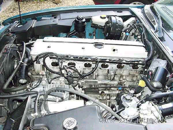
4 Liter Supercharged AJ16 engine in 95-97 XJR
|
The AJ16 engine is based on the previous AJ6 engine found in 3.2, 3.6 and 4.0litre XJ40 models. It features a host of detailed improvements, however, to provide increased power, torque and economy.
It is a straight six engine, with a pair of chain driven overhead camshafts and four valves per cylinder. XJR models feature a belt driven supercharged with associated intercooler, together with reducing the compression ratio from 10:1 to 8:1. Engine management is a significant evolution of previous systems, with diagnostics available only via the ODBII connector.
Experience so far has shown the engine to be fairly bullet-proof, though some XJR's have needed head gasket replacement.
Reprofiled cams were fitted to later models to overcome some problems with uneven idling.
2.1 - Cam Cover and Gasket ( Paul Stow,
December 1, 2001
)
An aging cam cover gasket may begin to seep oil, particularly around the cover bolt holes. The circular spark plug hole seals may also begin to weep, causing a build up of oil around one or more spark plugs. It is also necessary to remove the cam
cover when checking valve clearances and though this is not a frequent service item it is worth doing whenever the cover is removed.
To remove the cam cover, it is first necessary to remove the middle top section, by undoing the three torx bolts. Unbolt the epoxy encased ignition coils from the top of each plug and pull upward to free them from the spark plug.
Note how the wiring to each coil is of the correct length, and also note the arrangement of the wiring for the rearmost plug. Unclip the wiring and move the coils carefully out of the way. Also undo the clip and disconnect the breather hose from the right hand side of the cover.
The cam cover can be now removed by undoing the series of bolts around it's edge and lifting gently upwards. A little effort may be needed at first to break the seal.
If you are replacing either the cover gasket or a plug hole seal, it's worth doing all the plug seals and cover gasket at the same time. Also check the valve clearances following the procedure given below.
Seat the seals and gasket on the top cover prior to replacement. If necessary, use a little engine oil to help them stay in place. Make sure the gasket is aligned correctly, particularly around the halfmoon sections at the back of the head.
Replace the cover and gently tighten the bolts. Although precise torque and tightening procedure aren't critical here, follow good practice by starting with the left and right side bolts in the centre and working in diagonals to the ends.
Refit the wiring to the coils and then reattach the coils to the plugs. As with a normal HT lead, they may need a good push to click into place. Now gently tighten the coil fixing bolts - they don't need to be much more than finger tight, but there's no need to be afraid of them either. Refit the top centre cover and you're done.
2.10 - Oil system ( ,
)
2.10.1 - Oil and Filter Change ( Paul Stow,
December 10, 2001
)
Warm the engine through to thin the oil and ensure any particles are not sitting in the bottom of the sump.
Raise the car to gain access and, after placing a suitable container underneath, undo the sump drain bolt at the rear of the sump. When the flow has stopped, clean the bolt, copper washer and mating surface on the sump, and refit. It needs to be snug but not overtight. Leaks are usually cured by fitting a new washer.
Use a strap wrench or similar tool to undo the oil filter. Be aware the filter will contain oil, so keep your container underneath. Clean the mating surface on the engine block and use a finger to spread a thin layer of oil over the rubber sealing ring of the new filter.
Screw on the new filter until snug, then tighten approximately a further quarter turn. Hand pressure is normally adequate for this, but if you do decide to use a strap wrench, fit it close to the base of the filter such that you do not deform or damage it in any way.
Good oil filters feature an anti drain back valve which prevents oil draining back into the sump whilst the engine is stopped and therefore provides quicker lubrication when the engine is started. The valve can normally be seen as a piece of plastic behind the holes in the base of the filter. Jaguar and Fram filters are known to have this valve.
2.10.2 - Oil Cooler Bypass ( Paul Stow,
December 10, 2002
)
Some markets require a separate oil cooler to be fitted, the feed for which comes from the block beneath the oil filter. Where an oil cooler is not required, a bypass is fitted, consisting of a small 180 degree steel hoop-shaped pipe, again fitted next to the oil filter.
The connection is sealed by small rubber O-rings which do fail over time and produce an oil leak.
Replacement requires only unbolting and removal of the bypass pipe to gain access.
2.10.3 - Oil Pressure Sender ( Paul Stow,
December 10, 2001
)
The sender is located on the side of the engine block, underneath the inlet manifold toward the rear, and can be identified by the large diameter fixing nut. Removal is simple once you have access. On replacement, Jaguar recommend that a thread sealer such as Loctite 562 be applied to the exposed threads once the sensor has been screwed in by a thread.
Early X300's had a true pressure sensor, which is prone to erratic readings as a result of the carbon track of the potentiometer wearing out. Because of this, and customer concern over reduced oil pressure at idle, which is perfectly normal, later X300's and dealer repaired early models had a simple pressure switch fitted instead. This is linked with software reprogramming the instrument pack to cause the needle to sit either at the mid-point, or at zero dependent on the switch.
2.12 - Idle Speed ( Paul Stow,
December 1, 2001
)
The normal hot idle speed is 750 - 800 rpm in Park or Neutral and 650 - 750 rpm in Drive. The speed is determined by the ECU, which drives the Idle Speed Control Valve located in the throttle body, and it is not adjustable. Note the ISCV is a different device from that used on the previous AJ6 engine.
If the idle speed is incorrect and no other problems are apparent, check for a clogged or dirty throttle body, correct operation of the throttle position sensor or a weak throttle return spring.
2.2 - Valve Clearances ( Paul Stow,
December 1, 2001
)
Remove the cam cover as described a bove.
Each valve must be checking using a feeler gauge inserted between the back of the cam lobe and actuating bucket, when the lobe itself is pointing vertically upward. The engine can be turned in a clockwise direction using a socket on the crankshaft pulley bolt, and this can be made easier by removing the spark plugs first.
Adjustment is beyond the scope of many home technicians, as it requires removal of the camshafts and the insertion or removal of shims under the the actuators. The basic process is similar to that used on the XJ40 and described in the Haynes manual. Minor differences from specification are not a major cause for concern, but an undersize gap on an exhaust valve is likely to cause that valve to overheat and burn out.
Replace the cam cover as described above, checking the condition of the gasket and plug hole seals.
2.3 - Timing Chains ( Paul Stow,
December 1, 2001
)
The chains are of the duplex variety and are extremely reliable in service. An oil based tensioner is used, which also appears reliable. Rattling from the front of the engine, particularly when cold, may however be due to ageing or failing of the tensioner or plastic chain guides.
Note, however, that because the tensioner is driven by engine oil pressure, there may be a small noise for a couple of seconds at start-up if the engine has been left for some time and this is not a cause for concern.
2.4 - Inlet Manifold Removal ( Paul Stow,
December 1, 2001
)
Inlet Manifold removed
|
The procedure for this on normally aspirated models is slightly different to that for the XJR, as detailed below. However, the overall sequencing of tasks is essentially the same.
The manifold is a single casting with, in the case of the XJR, an intercooler welded onto the inlet side. The intercooler inlet is fed by the supercharger, which in turn is fed from the throttle body mounted underneath the inlet manifold. Incoming air is routed from the air filter over the top and down the rear side of the intercooler to reach the throttle.
Removal and refitting of the manifold is somewhat fiddly, but not complex. Make sure to note the position of pipes and electrical connections as they are removed, but Jaguar has helped here by ensuring most pipes and electrical connectors are shaped in such a way that they can only go back one way.
Begin by removing the trim cover from above the fuel injectors, which is held in place by three torx head bolts. Working along the line of injectors, squeeze the metal clip on the electrical connector to each injector and pull upward to release it. You will need to gently pull up on the plastic mounting which holds all the connectors in order to stop them clicking back in again. To avoid bending the mounting bar too much, you will probably need to release the next connector before the previous one can be fully freed.
Eventually all the connectors are released and can be moved away - it is possible to route the wiring over the front corner of the engine and so gain a bit more working space, but it is not necessary to trace and disconnect the injector wiring.
Slowly unbolt the fuel inlet and return pipes at the front of the injector rail / pressure valve assembly, allowing any remaining fuel pressure to dissipate and using a rag to mop up any spillage.
Disconnect the air intake hose. Again to make more space, disconnect the MAF connector ( halfway between air filter and manifold ) and remove the whole air intake trunking from the air filter end. Also disconnect the cam cover breather tube, which is routed between branches 5 and 6 of the manifold.
On the XJR, disconnect and remove the intercooler air inlet hose and unbolt the associated elbow. The plastic line going into this is for braking vacuum and is reluctant to come out of the elbow, so is best left in place. The elbow can be parked out of the way above the heater pump and hoses. The intercooler coolant hoses are at a fairly high point of the system, but it's less messy to drain at least some coolant out of the system before removing them. Also at this stage, unbolt the intercooler supporting bracket and associated dipstick tube bracket.
From under the car, disconnect the air duct feeding the throttle body from the rear side of the manifold assembly. Note that it is not easy to remove the rear ducting section from the manifold. Disconnect the breather pipe attached to the rear side ducting.
The manifold is attached to the head by nuts above and bolts between the inlet ports. Undo the nuts, which is easy, and undo the bolts, which is fiddly. You will need slim fingers or a pair of long nose pliers to remove the bolts when they are loose. Remove the connector support bracket from the rearmost mounting stud.
You may need to rock the manifold a little to free it, but it should now be possible to move it backward such that it is resting on the ends of the mounting studs. This gives you the extra clearance and movement needed to disconnect the wires routed down between ports 2 and 3 of the manifold.
On the XJR, these connectors link to the oil pressure sensor on the block, anti-knock sensor ( I think! ) on the block, throttle position sensor on the throttle body, Idle Speed Control Valve also on the throttle body, and Intake Air Temperature sensor on the underside of the intercooler.
Thread the electrical connectors between the manifold ports and out of the way. It is now possible to gently lift the manifold away, checking carefully for any forgotten attached pipes or cables. Beware of remaining coolant in the intercooler on XJR models.
Check the condition of the gasket. It can be reused if there are no potential leaks, but it's not expensive to replace. Ensure head and manifold surfaces are clean before refitting.
Refitting is the reversal of removal. The anti-knock sensor is tricky to get on, but will eventually give in. There are two similar style connectors, but one has a long lead and one a short lead, so you can't really mix them up.
Loosely attached the manifold using front and rear mounting studs, not forgetting the connector mounting bracket at the rear, whilst attaching the breather hoses, mounting strut, dipstick bracket and air ducting. Use long-nose pliers to get the bolts in between the inlet ports and get them all started before progressively beginning to tighten.
On XJR's, attached the coolant hoses and refill the system. For all models, replace the MAF and associated ducting, fuel send and return lines, the fuel injector connectors and their cover.
Check again carefully that all pipes and connectors have been replaced before starting the engine.
2.5 - Exhaust Manifold ( Paul Stow,
December 1, 2001
)
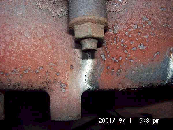
cracked exhaust manifold
|
Undo the six bolts securing the heatshield and remove it. On US models, remove the EGR.
Inspect the manifold for cracks. These are usually obvious, and may also have caused a dark line of soot on the manifold and heat shield underside. They cause increased noise and can affect ECU inputs from the Oxy sensor in the downpipe. Use a dentists mirror or similar to check the underside of the manifold.
A reasonable cure may often be made with a wet solution of exhaust putty pushed into the cracks, or a heat resistant epoxy, but a long term fix requires welding or replacement. Specialist welding is required, as a simple furnace weld is likely to warp the manifold and cause more problems.
Undo the exhaust downpipe to manifold bolts and lower the exhaust. This will be much easier if the bolts have been soaked in penetrating oil for a few hours beforehand.
Undo the manifold nuts and gently rock the manifold to release it.
Clean the manifold and head surfaces thoroughly before replacing the manifold, and use a new gasket. Otherwise, refitting is the reversal of removal.
If removing the lambda sensors from the downpipes, take care to mark them and reinstall each in it's original location. If they are reversed, the ECU cannot understandwhat is happening in the engine and will set a check engine error code.
2.6 - Supercharger Idler Pulleys ( Paul Stow,
December 1, 2001
)
The supercharger drive belt on XJR models runs over a fixed idler pulley, mounted in front of the thermostat block, and an adjustable idler pulley mounted directly on the front of the engine.
The adjustment is done by a movable pulley, sliding up and down on a threaded bolt. The top of this bolt can be seen from the right hand side of the car, point upward at a 45 degree angle just in front of the engine block. The head itself is just a squared off shaft, but can be turned with a decent pair of pliers.
These pulleys have been known to seize, thus throwing the drive belt. However, in itself this doesn't seem to cause any damage and, apart from significantly reduced power, the engine will continue to run without even illuminating the Check Engine light.
To remove the supercharger belt, first release tension on the belt with the adjuster.
Loosen the four fixing bolts which locate and hold the adjuster. The adjustment itself can now by turned, anti-clockwise to move the pulley down and release the tension. A good few turns are required, and a gentle tap on top of the pulley may help it to move initially. Once loose, the belt can be removed.
The idler pulley's can be removed simply by undoing the central fixing bolt. However, on the adjustment pulley it may be better to remove the mechanism as a whole by undoing for four fixing bolts. This will allow the pulley to be removed without straining against the adjustment bolt itself.
Refitting is the reversal of removal. The pulley bolts need to be tight, but not excessively so. Make sure
2.7 - Supercharger ( Paul Stow,
December 1, 2001
)
The supercharger itself is of the Eaton type, which differs from the Rootes model in having helical shaped vanes. The unit is reliable and the only required maintenance is to check the oil level, which can be read on the stick attached to the cap located at the front of the supercharger. Note the use of a special long life synthetic oil, available from dealers, and there is no recommended change.
Topping up is done by removing an allen type bolt located to the front left of the supercharger body.
The bypass circuit is actuated at idle or low throttle settings and consists of a pipe and vacuum actuated control valve located at the back of the supercharger allow air to pass directly from the inlet side to the outlet.
2.8 - Auxiliary Belt Tensioning ( Paul Stow,
December 1, 2001
)
This is done in the traditional way by adjusting the position of the alternator. It is safest, though not necessary, to disconnect the battery prior to undertaking this task, avoiding the risk of a spanner finding an uncovered live terminal on the alternator.
Loosen the long pivot bolt on which the alternator moves. Loosen the outer bolt on the threaded tensioning arm and give yourself enough adjustment to play with.
Using a bar or strong piece of wood, push the alternator outward, thus further tensioning the belt. This allows adjustment using the inner bolt on the tensioning arm.
If it is required to release tension, perhaps to remove the belt, then wind the inner bolt down the tensioning arm whilst continuing to push the alternator outward. Release the alternator and push inward to allow the belt to be removed.
When refitting, lever the alternator to obtain the correct belt tension and then wind up the inner bolt on the tensioning arm to hold the tension. Wind down and tighten the outer bolt on the tensioning arm, and finally retighten the pivot bolt.
3 - Cooling System ( ,
)
Overview
The core system is conventional, though of high thermal capacity and any movement of the gauge above normal should be investigated as a matter of concern. Likewise, warm-up should be quick with the gauge moving from cold to normal over a short period of time. Note though that the gauge is controlled by the ECU such that the centre points covers temperatures between about 70 and 98 degrees.
The main engine water pump is driven by the auxiliary belt. A second electrical pump is used for the heater circuit, mounted towards the rear right of the engine bay. XJR models also have an additional electrical pump for the intercooler circuit, mounted at the front right of the engine bay, together with an additional radiator mounted in front of the standard air conditioning and main radiators.
Two electrical fans are fitted, operating in two stages. They are controlled by a logic module which switches them on in slow ( serially connected ) mode when coolant temperature reaches 88.5C or air conditioning refrigerant pressure reaches 12bar. They are then switched to fast ( parallel connected ) mode when either the coolant reaches 100C or refrigerant reaches 22bar.
The control module itself is located at the front left side of the car, forward of the wheel arch near the EVAP system charcoal canister.
A problem was found with this system, in that the low-pressure refrigerant switch was unreliable, sometimes causing the fans to switch from standstill straight into fast mode with the subsequent start-up current causing the fuse to blow.
A dealer fitted workaround ( technical service bulletin ) was introduced which replaced the low pressure refrigerant switch with a wire link in the controlling circuit. This causes the fans to operate in slow mode whenever the air-conditioning is switched on.
3.1 - Thermostat Replacement ( ,
)
X300 thermostats appear to fail in the open mode after 4 - 5 years. This shows itself by the temperature gauge being slow to reach, or in some cases not achieving, the Normal mark. It is not unduly damaging to drive the car like this for a few days, but fuel economy will suffer and the throttle body is likely to get gummed up after a while, potentially causing it to stick partially open.
Thermostats can also fail in closed mode, causing rapid overheating. The car should not be driven whilst overheated otherwise severe damage will result.
To replace the thermostat, undo the two small bolts attaching the thermostat housing to the thermostat block. This can be found on the right hand side of the engine, attached to the large pipe leading from the top left of the radiator.
It may be necessary to pull quite firmly on the thermostat housing to break the seal. Note that a small amount of coolant will be spilt, though this can be avoided if you prefer by first draining some liquid by disconnecting the lower radiator pipe for a short time.
Remove the thermostat, noting which way it is fitted. Some vehicles do not have a gasket fitted, but if one is used then remove it. Carefully clean the faces of the thermostat housing and block.
It appears optional whether to use a gasket on replacement. It is not strictly necessary, but many feel more comfortable using a gasket or gasket compound.
Fit the thermostat into the block following the orientation of the old one; the actuating spring is normally on the engine side. Refit the housing, and tighten the fixing bolts. Whilst these need to be tight, excessive force will damage the threads.
Refill the cooling system to the maximum mark and run the engine up to operating temperature whilst checking for any leaks.
3.2 - Coolant Replacement ( ,
)
It is recommended that coolant be replacement every two years, as the anti-oxidants lose their effectiveness over time and leave the cylinder head at risk of corrosion. This in turn reduces cooling effectiveness and promotes head gasket failure.
Early models were also susceptible to a build up of sludge in the heater matrix, reducing heater effectiveness. The problem appeared to stem from the type of long life antifreeze used, and the best avoidance method is to use regular anti-freeze and change at two yearly intervals. Systems with the problem can be diagnosed as having a low heat output, assuming the engine is hot and the system set to defrost mode, and can generally be cured by repeated flushing.
Unless it is desired to completely flush through the system, it is not necessary to remove all engine drain plugs and remove the total amount of coolant.
The majority of the system can be drained by removing the header tank cap and disconnecting the lower radiator hose. The rush of fluid out of the system will also tend to pull any suspended particles with it.
Replace the hose and refill the system with a 50% mixture of quality anti-freeze and preferably distilled water. The exact percentage can be varied dependent on temperatures in your area, but it is safest to assume the residue of coolant in the engine is ineffective ad also bear in mind that as anti-freeze is less effective at cooling the engine than water, the mix should not exceed 65%.
Run the engine up to temperature with the header cap removed and heater switched to full to ensure any air pockets are released.
3.3 - Hose Replacement ( ,
)
It is recommended that hoses be replaced after 5 years service, to avoid risk of failure on the road which could leave you stranded.
With typical bad fortune, the hose most likely to fail is the hardest to access. It runs backward from the water pump alongside the engine to the steel engine water rail pipe and is subject to the surges in pressure which accompany sudden increases in engine speed, for example on kickdown.
Replacement of this hose and the water pump inlet hose, which also links the thermostat block, inlet manifold heater, interior heater, header tank ( and intercooler circuit on XJR models ) requires removal of the inlet manifold, following the instructions above.
Hence it is recommended that both are replaced together, along with the inlet manifold heater hose which is the small hose running from the thermostat block to the throttle body.
When refitting, note the performed curve in the water rail hose and ensure it is correctly oriented such that the hose fits correctly onto the outlets.
3.4 - Water Pump ( ,
)
It is recommended that hoses be replaced after 5 years service, to avoid risk of failure on the road which could leave you stranded.
With typical bad fortune, the hose most likely to fail is the hardest to access. It runs backward from the water pump alongside the engine to the steel engine water rail pipe and is subject to the surges in pressure which accompany sudden increases in engine speed, for example on kickdown.
Replacement of this hose and the water pump inlet hose, which also links the thermostat block, inlet manifold heater, interior heater, header tank ( and intercooler circuit on XJR models ) requires removal of the inlet manifold, following the instructions above.
Hence it is recommended that both are replaced together, along with the inlet manifold heater hose which is the small hose running from the thermostat block to the throttle body.
When refitting, note the performed curve in the water rail hose and ensure it is correctly oriented such that the hose fits correctly onto the outlets.
3.5 - Air Conditioning ( ,
)
The system under the bonnet is conventional and appears reliable. The compressor is located on the lower front left side of the engine, viewed from the front, and is driven from the engine auxiliary belt via an electrically controlled magnetic clutch.
There is an inline fuse visible on the wiring to the compressor clutch, which is fed from a relay located behind the headlights.
The pressure switched for the system can be found on the pipes towards the rear of the engine bay on the left side. These control the operation of the electric cooling fans, as described under ‘Cooling System’, and also protect the compressor by preventing it’s operation if refrigerant pressure is too low, typically following a leak.
Diagnosis of this can be done from the climate control panel, as detailed in 11.3 below.
To keep the seals in good condition, and therefore keep the refrigerant inside the system, it is important to run the a/c frequently even though it may not be needed for cooling purposes. Five minutes use every couple of weeks is all it takes to keep them lubricated and healthy.
3.6 - Air Conditioning Condenser & Filter/Drier Repl. ( ,
)
Failure of the condenser is one of the most common reasons for loss of refrigerant, as it is quite exposed at the lower front of the car. The filter/drier is mounted alongside the condenser and needs the condenser to be removed for replacement.
To remove the condenser, first remove the radiator top panel which crosses the width of the car at the front of the bonnet area. It is secured by a number of large torx bolts which appear to frequently seize up. If necessary, they will need to be drilled out, or the heads ground off, but fortunately load on this panel is not high and loss of one or two bolts does not appear to be a problem.
Locate the pipes leading to the condenser as they pass to the left side of the main radiator. The union for one pipe is a few inches into the main engine bay whereas the second is on the filter/drier unit, mounted on top of the condenser and therefore harder to access.
Undo the unions slowly, listening for refrigerant pressure. If there is any pressure, then you don’t have a leak and the condenser doesn’t need replacement.
The top of the main engine radiator can be pushed gently backwards and the condenser & filter/drier then removed by pulling them upward. On XJR models, the upper hose for the intercooler radiator, mounted in front of the condenser, makes this more difficult but it is just possible without removing the hose.
The area around the mounting lugs for the condenser is a known rust spot and so you may consider treating it with a rust-proofing agent prior to refitting.
If you have to replace the condenser, replace the filter/drier at the same time as these do wear out and otherwise need replacement on their own.
When refitting the condenser, carefully lower it into the space and from underneath ensure it is settled correctly onto the locating posts. Reattach the pipework and refit the top panel.
The system works at high pressure so ensure O-rings are in good condition and ensure unions are tight during refitting. Always use two spanners on the union to avoid stresses other parts of the pipework when loosening or tightening the unions.
3.7 - Coolant Cap ( ,
)
The cap maintains pressure in the system, with venting controlled by a spring under the brass centre piece of the cap, which lets excess pressure escape via channels in the threads.
Failure of the cap is indicated by traces of coolant on the top of the header tank, accompanied by coolant loss from the system. Failure can occur if the spring becomes weak or if the rubber sealing washer becomes worn or deformed.
4 - Fuel System ( ,
)
Overview
Fuel is continuously circulated by an electric pump located within the tank itself. A filter is located under the car floor, beneath the tank. A vacuum driven regulator controls the fuel pressure in the injector rail, with the injectors themselves being controlled by the main engine ECU.
Be aware the system operates at high pressure, so leave the car to stand overnight, or very cautiously relieve the pressure by opening a joint in the fuel lines a fraction at a time using a cloth to mop up spilling fuel.
The continuous circulation of fuel causes the fuel tank to act as a heat sink, keeping fuel temperatures down and preventing vapourisation. A long journey on a hot day will, however, cause fuel in the tank to become warm. This is normal and no cause for concern.
4.1 - Fuel Filter Replacement ( ,
)
This is rarely needed as part of a normal maintenance routine, but is necessary should the fuel system be contaminated or low fuel pressure be suspected.
Unbolt the unions, and be prepared for spillage. Remove and replace the filter, then refit the unions. Use new copper washers to avoid subsequent leaks.
4.2 - Fuel Gauge Sender ( ,
)
Early X300 senders can develop a problem that results in the gauge not registering above three-quarters and/or being generally inaccurate. This is caused by contamination of the electrical track along which the wiper arm operates. Jaguar recommends a replacement unit, though some people have fixed existing unit by cleaning the track as follows.
To avoid spillage, the fuel level in the tank needs to be as low as possible and at least below an eighth full. The sender is located at the back of the tank and can be accessed by removing the trim panel at the back of the boot/trunk.
Remove the float pivot from it's plastic mountings. Clean the electrical track and contacts with a fibreglass pencil or similar gentle abrasive. Ensure the contacts are adequately tensioned before reassembly.
When refitting, ensure the arm movement is clear of the fuel pump wires inside the tank.
4.3 - Throttle Body Removal and Cleaning ( ,
)
Periods of cold running, perhaps caused by a sticking thermostat, will cause the throttle body to become gummed up internally, potentially causing the throttle to stick partially open and also affecting Idle Speed Control Valve (ISCV) operation. It can also be the cause of an uneven or lumpy idle.
On the XJR, the throttle body is located under the inlet manifold so this must be removed first following the instructions above. Those with a ramps or a hoist may be able to gain sufficient access from underneath.
Release the throttle cable by carefully using a pair of long noses pliers to push off the retaining clip. Also disconnect the vacuum hose from the cruise control actuator.
Unbolt the heated part of the manifold, releasing the coolant pipes as necessary, and then unbolt the throttle body itself. The ISCV can be identified as a small nozzle in a drilling in the side of the main orifice, which controls the amount of air bypassing the main throttle butterfly.
On the bench, use carburettor cleaner or a similar solvent to clean out the body, butterfly and ISCV. Allow the cleaner to get into the ISCV drillings, but hold the body so as to avoid running down into the Throttle Position Sensor, which is contained in the plastic housing at the end of the throttle butterfly shaft.
Reassembly is simple. Make sure the cruise control actuator arm can fully actuate and release the throttle butterfly. No gaskets are used, so to avoid vacuum leaks, ensure the mating surfaces are smooth and clean. Bolt everything up and reattach the throttle cable, retaining clip and cruise control vacuum hose.
4.4 - Throttle Return Spring ( ,
)
Early models may develop a problem whereby the engine rpm will not drop to the correct idle speed. This can be caused by a dirty throttle body causing the throttle to stick ( see above ), a weak throttle return spring, or a combination of both.
Jaguar did issue a bulletin (tsb) to replace the springs on earlier models and the spring is available from dealers. If the problem persists after cleaning the throttle body, or you wish to replace it anyway, the newer part is available from the dealers.
These fitting instructions are based on the XJR model with cruise control, and so details may vary on other vehicles.
On the XJR, the throttle body is located under the inlet manifold so this must be removed first following the instructions above. Those with a ramps or a hoist may be able to gain sufficient access from underneath.
The throttle return spring is attached to the bell crank actuated by the throttle cable and is now simple to remove and replace. Ensure throttle action is smooth and that it now closes fully by pushing gently on the bell crank to ensure no further movement. Refit the inlet manifold.
4.5 - Throttle Position Sensor Replacement ( ,
)
Gain access to the throttle body, as described in 4.3 above, and locate the TPS. It is a square black plastic unit, mounted on the end of the throttle shaft with a three wire electrical multi-plug.
Disconnect the multi-plug, undo the securing screws starting with the one at the front of the engine, remove the retaining plate and then the sensor itself.
When refitting, ensure the sensor engages correctly on the spindle. The sensor is spring loaded and must be turned slightly to then refit the retaining plate and fit the securing screw towards the rear of the engine. Don't fully tighten. Fit the front securing screw, then tighten the rear screw. Refit the connector.
At this stage, the Jaguar workshop manual says that the ECU must be reset to work with the new sensor. This is probably to allow it to understand the characteristics of the sensor at idle and full throttle opening and therefore not required if replacing the same sensor.
4.6 - Fuel Feed Hoses ( ,
)
A helicopter noise from under the bonnet, coupled with a pulsing in the fuel hoses, indicates a fuel damper or hose. The fuel damper is inline with the hoses and replacement is simple, but remember to leave the car to stand overnight or release fuel pressure carefully when undoing the pipe unions.
4.7 - Fuel Filler Drain ( ,
)
There is a small water drain positioned alongside the fuel filler. Ensure the drain is kept free from debris, as a build up of water may then find it's way into the tank. The drain tube itself can be accessed from inside the boot after removing the side trim panel.
5 - Engine Electrical, Ignition and ECU ( ,
)
This is of the conventional 12V negative earth type. The battery is located under the floor of the boot alongside the spare wheel.
Low battery voltage can cause incorrect operation of the engine ECU, resulting in difficulty starting the engine. Modern batteries are also prone to rapid failure so always suspect this before more complex items.
Various electrical systems continue to function for a few minutes after the ignition has been switched off and the car locked, so checking for unexpected current drain, wait for 5 minutes or so after shutdown with all doors closed. Typical drain is around 80mA.
The ignition system on the AJ16 differs from it AJ6 predecessor in having an ignition module fitted to the top of each spark plug. This is a significant reliability boost in that a central coil, distributor cap and HT leads have been eliminated and it is hard for moisture to enter the system and allow the spark to leak away.
5.1 - Spark Plug Choice ( ,
)
The subject of spark plugs seems to cause as much debate as tyre brands, but in general it seems the AJ16 engine is as happy on the factory standard Champion RC9YCC as any other more exotic types. Some engines appear to have problems with more expensive plugs, with rough idle and misfires particularly when starting from hot.
To improve idle quality, Jaguar recommended a change to the slightly hotter RC12YCC plugs. These were fitted to XJR models in the factory from ’97.
5.2 - Spark Plug Replacement ( ,
)
Remove the cap on the engine top cover by undoing the three torx head bolts.
Working methodically along the engine, undo each epoxy cased ignition coil and gentle pull upward to free the assembly from the plug.
Use a conventional plug socket and extension bar to undo and remove the plug. Unless the engine has recently been started and not warmed up, the plugs should be a light brown/grey colour. Whiteness can indicate a lean mixture or water in the cylinder from a blowing head gasket. Dark and sooty suggests a rich mixture, but is normal when the engine has just been started and stopped when cold.
Gap the new plugs to 0.035" / 0.09mm and fit by tightening until they feel tight, but don’t overtighten. Reattach the ignition modules and gently rebolt them in place. Refit the engine cover top cap.
5.9 - Troubleshooting ( Jag_Fan,
)
Following the advice of Mark Stephenson - X300 Admin - I have split my guide into 5 pieces in order to be able to post the complete guide. This is part 1 of 5.
I would like to point out one thing first: You can call me an expert when it comes to electronics H/W, F/W or S/W design but I am NOT an expert when it comes to combustion engines. So, what I am telling you here - as far as things other than electronics are concerned - I just learned in the past one or two weeks.
We will start with some tests to figure out what the possible cause for you engine dying or hanging at some 1,500 rpm might be.
TEST #1 - WEAK BATTERY CAUSING HIGH RIPPLE CONFUSING THE ECM
Borrow a starter battery from a friend's car which is fully charged and not too old. It doesn't matter if the amp-hour rating doesn't match the 72 Amp-hours of the X300-battery. Even 45 amp-hours will do. Replace your ''old'' battery with this borrowed battery and check if the problem is still there. If you don't observe ''engine dying'' or ''hanging at 1,500 rpm'' any longer, get yourself a new battery and you're done.
TEST #2 - TOO MUCH OR NOT ENOUGH BYPASSING COMBUSTION AIR
Now, here is what you should do to figure out if your problem is caused by too much (hanging) or not enough (dying) combustion air
bypassing. This can - but must not be necessarily caused by a weak battery
Once you observe the correct idle speed of some 800 rpm with the gear shifter in ''D'' position with the car stopped and with the
engine already warmed up, pull the parking brake and leave the shifter in ''D''. Get out of the car and pull the plug which connects that four wire connector to the ISCV. This way you will have a constant amount of combustion air passing by no matter what the ECM does. Now, drive the car for a couple of miles and check whether the problem is still there. You will of course get an MIL indication in the dashboard telling you that there is something wrong with the engine. This is due to the fact that the ECM has a self test system onboard which also checks feedback concerning the ISCV. You can turn the engine off, start it again, and you can drive the car like this for a couple of days if you wish. You will observe some ''unusual'' behavior when releasing the gas pedal at higher speeds but that's about it. And of course you will have a slightly accelerated idle speed with the gear shifter in the ''N'' position at some 1,000 rpm.
If the problem is still there you have a mechanical problem which has nothing to do with the ECM control mechanisms.
If it is gone you either have an electrical control problem (not necessarily the ECM itself - please refer to the other tests) or the plunger of your ISCV is stuck.
TEST #3 - IDLE SPEED CONTROL VALVE
To make sure that the ISCV plunger is moved correctly remove the ISCV but leave the connector plugged. Now turn the ignition on (do not start the engine) and observe the plunger movement. Turn the ignition off and observe the plunger movement again. If it is moving properly in and out again every time you turn the ignition on or off the plunger and the stepper motor attached to it should be ok.
TEST #4 - THROTTLE POSITION SENSOR
You should now check the Throttle Position Sensor. It delivers one of several input signals the ECM uses to control the ISCV. There
is a gold plated potentiometer located at the bottom of the throttle body and which is fed by 5 V through the ECM. With the ignition on you should check with an analog voltmeter whether the voltage is moving smoothly up and down while you are pushing the gas pedal smoothly up and down. You can attach the positive probe to pin 12 at P1105 of the ECM with the connector attached to the ECM and the negative probe to ground.
There is also another way. Turn engine and ignition off. Simply use an analog ohm meter and attach your probes first to the wiper and one of the two outer pins of the potentiometer and see if you get smooth movement on your ohm meter while pushing down the gas. Then repeat this procedure by using the other outer pin of the potentiometer.
You can either perform this test directly at the potentiometer with the connector removed. Or you can pull P1105 from the ECM and put
your ohm meter between pins 12 and 11 and then between 12 and 7.
If you observe interruptions or ''jumps'' of the ohm meter's needle you found the cause of your problem. You can try to ''repair'' this by using contact spray on the potentiometer. But be careful when taking that part of the throttle body apart. In the workshop manual the say that after renewing this potentiometer the ECM will have to be reprogrammed. This means that some sort of adjustment will have to be performed which is done by changing some parameters in the ECM's F/W. So you should try not to change the position of the potentiometer.
If the potentiometer is ok as well we can be pretty sure that your problem is caused by faulty output signals sent to the ISCV by the ECM.
TEST #5 - HIGH BOARD VOLTAGE RIPPLE CONFUSING THE ECM
You can now try to feed the ECM with a separate battery in order to avoid any supply voltage ripple confusing the ECM. Pull the fuse
of the ECM in the corresponding fuse box (see Vehicle Care Manual of you car). Take a broken fuse or produce one by blowing the fuse
section of a new fuse and remove the upper part of the plastic material so that you are able to access the top of the contact pins.
Solder a wire AWG 14 or better (copper diameter greater or equal to 0.064 inch) to the top of one of the contact pins. Put this ''adapter-fuse'' in the place of the original one in such a way, that the soldered wire is at the end that leads to the ECM. (This is the end that doesn't carry voltage from the car's battery.)
Connect another AWG 14 wire to chassis ground near the location of the ECM. Connect this ground wire to your borrowed battery's
negative post and connect the wire from the ''adapter-fuse'' to the battery's positive post.
Keep both wires as short as possible, just that they are long enough to reach the borrowed battery placed in front of the front passenger's seat. Take the car for a test drive and check if your problems are gone now.
Or you can just disable the generator. In order to do this I recommend you to remove the attached regulator. Now, the battery will not be charged any longer. But with a new and full battery and no lights and fans on you can drive the vehicle for at least one hour. However, you should have a spare battery with you or at least a starter cable - just in case. Anyway, I consider the ''separate battery test'' the better option as you do not have any other EMI sources ''polluting'' the supply voltage of the ECM.
If the problem is still there you can be sure that high ripple caused by a faulty (generator) regulator or rectifier isn't the cause of the problem. You will then have to repair the ECM as described later in this document.
If the problem is gone you should now try using a new starter battery. But first remove the separate battery and put the original ECM fuse back in its place.
If with the new battery the problem is coming back you should check the board voltage for high ripple. Please see Test ''Test #6'' for
details
TEST #6 - GENERATOR AS CAUSE OF HIGH RIPPLE
With a new starter battery high ripple can also be caused by a faulty regulator (JLM 11144) or by a faulty diode in the rectifier
assembly (JLM 11147). Part numbers referring to the XJ6.A first simple test is using an oscilloscope for checking the
ripple on your 12 V board voltage. A good point to attach your probes would be the front seat cigar lighter jack. Don't attach
the probes directly to the battery. With the engine running at 1,500 rpm and all lights and fans off the ripple should not exceed
0.5 V. If it is greater than that you probably have a generator problem, regulator or rectifier that is.
To check whether the rectifier is the cause of the high ripple - one or more of the diodes are not working (open circuit) - you will
again need an oscilloscope. As there should be 6 half sine waves per revolution from the generator you will still be able to observe
a minor ripple which exactly should show those 6 ''peaks'' on the board voltage in equidistant intervals. If the intervals are not
equidistant then one or more of the diodes are broken.
As the diameter of the generators pulley is smaller than the one at the engine the rpm's of the generator will be greater than the ones of the engine. I don't know the exact ratio. Let's assume the ratio is 3.
This would result in 2,400 rpm at an engine idle speed of 800 rpm or 40 revolutions per second of the generator. With 6 ''pulses'' per generator revolution this would result in 240 peaks per second on the board voltage.
You should set the oscilloscope to AC coupling and to 5 msec/unit so you can observe 12 peaks at idle. (Note that this is only correct if the ratio I assumed to be 3 is correct. Otherwise adjust your scope accordingly, so that you see something between 6 and 12 pulses on the screen). It might be a bit tricky to trigger the scope that way! Make sure that you don't see any jitter. Otherwise you cannot observe if all peaks are equidistant.
If all pulses are equidistant than the rectifier works fine. One missing peak represents one faulty diode.
And this is how the regulator works:
The output voltage of the generator depends on the revolution per minute and the strength of the magnetic field generated by a special coil. In order to keep the voltage at a constant level this magnetic field is controlled by a power transistor which itself is controlled by a regulator which actually is just a comparator. This comparator compares the generated voltage fed to a voltage divider with a fixed voltage generated by a resistor and a zener diode. Depending on the generator voltage the transistor feeds this additional coil with more or less current to keep the generator voltage at a constant level.
The conclusion you can draw from these tests is as follows. If the rectifier is ok AND you have a new starter battery AND you do not
experience the problem with the regulator assembly removed from the battery, you should try renewing the regulator.
TEST #7 - ECM MALFUNCTIONING DUE TO DEGRADED ELECTROLYTIC CAPACITORS
There are two ways of ''repairing'' this.
a) Real Repair
You will have to open the ECM and - just to make sure - replace all axial and radial electrolytic capacitors. If you don't want to replace all of them you should at least replace the ones that read 47 µF or above. The capacity should be the same or up to twice the capacity, i.e. you can replace e.g. a 47 µF capacitor with a 68 µF or a 100 µF capacitor. The voltage rating must be the same or higher with no upper limit. Usually 16 V should be enough. Note, that you can also solder new capacitors in parallel to the old ones. But in this case the capacity should be the same as the original one.
Make sure of all safety precautions concerning protection against ESD (Electrostatic Discharge). Don't use soldering irons without an isolation transformer!
b) Substitute Repair
With this repair method you don't have to open the ECM. Instead you will have to attach a filter between the ECM and its original 12 V power supply. The problem is that this way you will have to filter the sum of all currents drawn by the ECM. As the ECM is also feeding components like spark plugs for instance, it will have to be a pretty big filter.
What you need is a so called low pass filter similar to a filter used for bass loudspeakers. However the values of the capacitors will have to be much bigger due to the lower cut off frequency needed for the ECM application.
A simple low pass filter consists of a choke (coil) which is in series between 12 V and the ECM and a capacitor between the 12 V supply input of the ECM and ground near the ECM. If you use more of these in series ripple rejection is of course better.
The choke should have 1 mH (milliHenry) and the capacitor should have 100,000 µF (microFarads) and at least 16 V. The bigger the better is applies to both components.
TEST #8 - ECM MALFUNCTIONING DUE TO BAD SOLDER JOINTS
This is what I once experienced with the lamp modules of my old XJ40: The were many bad solder joints which caused broken bulb
messages being displayed by the board computer all the time until I re-soldered everything in those modules.
If you have the time and are able to do this try to re-solder all solder joints on the printed circuit board of the ECM. But there
is of course still the chance of faulty components which you cannot find and/or replace that easily.
But there are also a lot of used ECM's for sale and if you consider to get yourself such a used ECM make sure that it is the correct
one for your car. From the Workshop Manuals and the Part Lists I learned that there are many different ECM's. So, make sure the
part number matches your vehicle. In case you don't have access to that information please let me know and I will check it for you if
you give me the details of your vehicle including VIN.
TEST #9 - OTHER FAULTY SNESORS
There are a number of sensors that produce signals monitored by the ECM. And the ECM controls the ISCV based on those signals. The
important and most likely ones I discussed here. But there are also the ''Intake Air Temperature Sensor'' and the ''Mass Airflow Meter'' that might have an influence concerning the dying or hanging problem. But to my understanding this is rather unlikely. And if you suspect the Intake Air Temperature Sensor just replace it with a fixed resistor for a try.
SOME FINAL WORDS
Please remember that all the tests I tried to describe here are only referring to one single cause of the dying or hanging problem, i.e. the wrong amount of bypass air fed to the engine. Even though this is the most likely one in my opinion there are many other possibilities which I did not and could not cover here.
6 - Engine Management & Emissions Control ( ,
)
Overview
The engine ECU receives input signals from a number of sensors and uses this information to control the operation of the ignition system, fuel injectors, Idle Speed Control Valve and other sundry equipment.
Any sensor values which appear incorrect or out of range, will set an error code and cause the Check Engine light to come on. The ECU will then set a default value for that sensor and continue to operate as best it can with the information. Although itself commonly suspected to be the source of trouble, problems can almost always be traced back to a failed input sensor or connection.
Diagnostic information is output via the ODBII connector, which can be found as a plug to the right side of the steering column. The codes can be fully interpreted by the Jaguar Diagnostic equipment, but commercially available software using a laptop computer will allow a reasonable level of diagnosis to be undertaken.
In addition to the catalytic converters, cars in the US and some other markets are fitted with Exhaust Gas Recirculation and Air Pump equipment. The Evaporative Emissions system is also fitted in most markets.
The ECU does 'learn' the car over a period of time, but can be fully reset by disconnecting the battery for an hour.
6.1 - MAF - Mass Airflow Meter ( ,
)
The MAF is situated in the intake air ducting between the air filter and inlet manifold. It measures the volume of air entering the engine and is therefore a major input to the ECU's operation. As a result of the low voltage of the output signal, the connectors are gold plated and should always be kept scrupulously clean.
6.10 - Evaporative Emission Control ( ,
)
This system captures fuel vapours from the tank and throttle body which would otherwise be released into the atmosphere. Vapour from the tank is collected via hose in a charcoal canister mounted behind the left front wheel. When the engine is running, the vapour is pulled by inlet vacuum into the throttle body and burnt as part of the normal combustion process. This process is controlled by the ECU to only occur when the engine has warmed up.
6.11 - Traction Control ( ,
)
This system reuses the speed sensors fitted to each wheel for ABS operation to detect if the rear wheels are turning faster than the front, indicating that wheelspin is occurring.
In this case, the system backs off the throttle, reducing engine power until the spin is eliminated. This is done by the motor fitted effectively in line with the throttle cable, on the left side of the engine bay ahead of the coolant plumbing, valves and pump for the internal heater. Operation can be felt through the throttle pedal.
6.2 - Intake Air Temperature ( ,
)
On XJR models this is measured by a sensor built into the base of the supercharger. The sensor decreases in resistance as temperature increases. It has a limited effect on operation, retarding the ignition timing as temperature increases in order to reduce the possibility of pre-ignition.
6.3 - Coolant Temperature ( ,
)
This sensor is on top of the thermostat housing, next to the sensor which drives the temperature gauge, and is one having the locking two pin connector. As with the AIT, it decreases in resistance as temperature increases, but it does have a significant effect on operation, being used to determine cold start and running conditions.
6.4 - Throttle Position Sensor ( ,
)
This is a simple potentiometer attached to the throttle shaft that varies the voltage signal to the ECU dependent on throttle opening. Bad operation or adjustment can result in a high idle speed or hesitation as the ECU is fed misleading information.
6.5 - Crank Position Sensor ( ,
)
This is an electro-magnetic device that understands the crankshaft position by recognising a missing tooth on the crankshaft timing gear. Pulses from the CPS are critical to normal operation as the ECU cannot otherwise determine when the fire the ignition and injectors.
The CPS is mounted on a bracket at the front of the engine, half-way down to the left. It can perhaps be found easiest by identifying the connecting wire and connector leading down the front side of the engine. Replacement is simple, requiring only electrical disconnection and the component to be unbolted from it's bracket.
This component is known to fail at high mileages, and can cause erratic running prior to failure. As a result, some advocate replacement at 80-100K miles as a preventative measure.FS
6.6 - Oxy (Lambda) Sensors ( ,
)
These devices are fitted into the exhaust downpipe and measure the oxygen content of the exhaust gasses. For correct operation it requires operation of an inbuilt heater element and a reference atmosphere, which is obtained from normal air entering along the wiring harness. The device changes resistance dependent on the exhaust gasses and this change is measured by the ECU. Note this is different to earlier models, where the sensor produced a small voltage for the ECU to measure.
European models have two sensors, one in each downpipe. US specification models have four sensors, with the second pair fitted after the catalytic converters to allow the ECU to monitor their effectiveness.
If sensors are removed, ensure each is connected to the correct location and wiring, otherwise the ECU cannot understand the behaviour of the engine and will set a check engine error code.
When the engine is in warm-up, the ECU ignores the sensors and operates using a reference set of information. Once sufficient temperature has been reached, the ECU will begin to use the sensor outputs to control the precise fuel/air mixture of the engine.
In correct operation, probing the voltage with a DVM should show it continuously swinging between 0V and 5V. The component is easy to damage chemically, so do not use solvents such as WD40 to clean the connectors.
The wiring for the sensors is routed to the rear of the engine over the transmission bellhousing, located in place by metal clips. If the oxy sensors appear ineffective, resulting in high CO% readings, check the insulation hasn't frayed at the clips and effectively earthed the sensor.
6.7 - Speed Sensor ( ,
)
This is shared with the speedometer and is mounted in the rear differential unit.
6.8 - Exhaust Gas Recirculation System ( ,
)
This aims to reduce emissions by reducing combustion temperatures in the cylinders. This is done by recirculating exhaust gasses back into the inlet manifold under certain engine conditions, typically part throttle operation, as determined by the ECU.
The EGR pipework leads from the exhaust side, under the exhaust manifold, around to the inlet manifold. On most models, the electrically operated valve is located on the inlet side, but on XJR models it is mounted adjacent to the exhaust manifold itself.
An intake temperature sensor on the intake side near the EGR inlet can detect the correct operation of the system and will set an error code in the ECU if this does not occur. Common causes are failure of the valve itself, or the pipework becoming blocked, particularly at the entry into the inlet manifold.
There has been a recall on '95 - '97 models to overcome blockages by forcing the ECU to periodically operate the valve. However, this has itself caused problems with '95 models and a second recall is being introduced.
6.9 - Air Pump ( ,
)
This is designed to reduce emissions by injecting fresh air into the exhaust gasses to promote their oxidisation. It's operation is controlled by the ECU and it is active only during warm-up, before the Oxy sensor input begins to be used. The pump is driven by an internal motor.
7 - Transmission & Drivetrain ( ,
)
Overview
From ’95 - ’97, normally aspirated models were fitted with ZF HP24F four speed automatic transmission, with the GM 4L80E unit fitted to the XJR and XJ12. From ’97 onwards, the basic power train was changed to the eight cylinder engine and five-speed automatics.
All the transmissions are electronically controlled, with the transmission ECU closely linked to the engine ECU and taking input principally from road speed, engine speed and MAF and TPS. Retarding the ignition during a change smooths gear changes. A Sport/Normal mode switch is fitted, with Sport mode being more sensitive to input from the TPS ( throttle pedal sensor ), providing more responsive downshifts and also holding higher rpms. The degree of ignition retardation and time for gear shifts is also reduced giving a sportier feel.
The torque converter has a lock-up, which comes into effect when cruising at 52mph or above in normal mode, or at a slightly higher speed when in sport mode.
Kickdown is operated by an electrical switch under the throttle peddle on the floor of the car.
An interlock is fitted, to avoid the transmission being moved from Park before the engine is running and the brake pedal depressed. This can be overridden using the lever under the star shaped cover on the J-gate selector.
7.1 - Fluid Check ( ,
)
This should be done with the transmission at normal operating temperature with the engine running, so ensure the car has been driven a few miles first. Cycle the J-gate from Park to Drive and back again a couple of times, then with engine idling, check the fluid level.
Also look for any contamination of the fluid and for a burnt smell indicating a change is required.
7.2 - Fluid Replacement ( ,
)
Locate the transmission sump drain plug, undo to allow fluid to drain, then refit.
Undo the transmission sump retaining bolts and carefully lower the sump pan, taking care as it will still contain some fluid. Remove the gasket and clean the mating surfaces with a rag or plastic scraper if necessary.
Carefully clean any metallic swarf from the magnet, and clean thoroughly to ensure no metal is returned into the system.
Undo the torx head bolts holding the filter in place and remove the filter along with it’s associated O-ring.
Fit a new O-ring and filter, then refit the sump pan and gasket, tightening the bolts in a diagonal pattern until snug. No need to overtighten. It is not normally necessary to use a new gasket, though some recommend it.
Refill the transmission via the dipstick tube and recheck the fluid level.
7.3 - Transmission Mount Replacement ( ,
)
The transmission itself is normally free to move up and down within a limited range of travel. The mounting is above the top rear of the transmission and comprises a spring, various cups and washers, and a foam isolator. This is prone to wear, resulting in the transmission banging against the underbody on bumpy roads. There is also a travel limiter strap fitted, restricting the downward movement of the unit.
To replace the mount, first jack the car as high as you can to make room for working. Unbolt the exhaust downpipe and allow it to hang out of the way. Put a jack or stand under the body of the tranmission to hold it whilst the mount is remove.
Now put a jack under the mounting crossbrace, and undo the four fixing bolts. Gently lower the crossbrace on the jack until you can access the clip and pin of the retaining strap and remove them.
The crossbrace and mount assembly can now be removed, disassembled, cleaned and reassembled with new foam or rubber isolator.
Refit the travel limiter strap and associated clip, and then refit the crossbrace. Tighten securely, then remove the jacks and check for free movement of the transmission and that it appears to sit at the same height as previously.
7.5 - Rear Differential ( ,
)
7.5.1 - Differential Fluid Level ( ,
)
The fluid level can be checked by removing the filler plug at the rear of the unit and feeling inside with a finger. The level should be just at the bottom of the hole.
Do not confuse the filler plug with the breather, which is located higher on the unit and has a plastic fitting attached.
It is unusual for the fluid level to change unless a seal has failed, in which case oily deposits will be seen around where the half shafts or drive shaft enter the unit.
7.7 - Tyres ( ,
)
Choice of tyre is one of those subjects that provokes much debate. As a minimum, however, you should choose a tyre with adequate speed and load ratings for the car. The speed rating is important because although you may not plan on going that fast, it does affect the construction of the tyre and hence it’s load bearing and handling characteristics.
Tyres sizes are defined by the width, ratio of sidewall height to width ( known as the profile ) expressed as a percentage, speed rating and wheel diameter so, for example, a 245/45ZR17 has a width of 245mm, a 45% profile meaning the height of the sidewall is 45% * 245 = 110mm, fitted to 17" wheels.
If changing tyre size, then for the speedometer to remain accurate you need to maintain the same overall diameter. This can be calculated as the wheel size plus twice the sidewall height ( converted to inches ), so for the above tyre it is 17 + 2 * (110/25) = 26".
The Jaguar suspension set up, particularly with the wide low-profile tyres found on XJR models, is quite sensitive to tyre pressure. Low or uneven pressure will tend to result in a lot of ‘tramlining’, following the contour of the road making for an unstable drive. For the XJR, about 34psi seems to be right. On the standard car, 32 psi is recommended, going down to 28 psi to gain a more comfortable ride when unladen and not cruising at high speed.
8 - Brakes ( ,
)
Overview
The system has discs ( rotors ) on all wheels, with single piston calipers at the rear and single or double piston ( on some later models ) calipers at the front. The handbrake utilises a separate drum and shoes mounted inboard from the main braking system.
Power assistance is provided by engine vacuum an accumulator. The pedal should be capable of being pumped five to seven times after the engine is switched off before becoming hard, any shortfall suggesting a weakening accumulator or seals.
The ABS system uses speed sensors on each axle, coupled with electronically controlled valves in the main valve block to hold back braking pressure when a wheel begins to lock. The system is fail-safe, such that the valves will remain open and the system will act like a normal non-ABS system in the event of a system problem.
The speed sensors are also used by the Traction Control system.
Note that no pad wear indicators are fitted.
8.1 - Brake Pad Renewal ( ,
)
Remove roadwheel. Check brake disc (rotor) for adequate thickness and absence of warp, and replace if necessary.
Unbolt the caliper guide pins using a 7mm allen key. The caliper can now be moved to one side and the pads pulled out. Avoid putting any strain on the caliper brake fluid pipe.
Put the caliper approximately back in position and undo the bleed nipple. Attach a piece of rubber pipe looped upward then leading to a jar on the ground, or use a brake bleeding kit. This will prevent air getting into the system. Releasing fluid when pushing the pistons back is significantly easier than pushing the fluid back up through the valve block and avoid risk of damaging or contaminating the sensitive ABS valves.
It is now necessary to push the piston back to be flush with the cylinder, so allowing sufficient space to install the new pads. To not exert force directly onto the piston, but use the old pad instead. Pulling the caliper toward you will push the piston back, as will levering between pad and disc with a stout piece of wood. Do not use metal which would damage the surface of the disc. Tighten the bleed screw and remove the old pad when the piston is pushed back.
Clean the caliper and coat the guide pins, piston head and areas of the caliper in contact with the pads with copper gresase. This will make removal next time that much easier!
Insert the new pads and rebolt the caliper in place.
8.2 - Brake Disc Renewal ( ,
)
Undo the brake caliper, remove the pads, and suspend it out of the way without straining the fluid pipe.
Unbolt and remove the caliper mounting bracket.
Undo the disc retaining screw if fitted. The screw is only used in production to hold the disc in place whilst moving down the assembly line.
It should now be possible to remove the disc from the hub. In practice, it is often necessary to spray WD40 where the disc meets the hub, then use a hammer on the disc to initially release it. On rear discs, it may also be necessary to back off the handbrake adjustment.
Clean the hub and refit the new disc. Bolt the caliper bracket into position, fit the pads to the caliper and refit the caliper.
8.3 - Brake Bleeding and Fluid Replacement ( ,
)
Bleeding can be done with a proprietary bleeding kit, or by the more traditional methods. Fluid replacement is achieved through an extended bleeding process, ensuring sufficient old fluid has been removed from the system to be replaced by new.
Bleeding should be done at each wheel, starting with the right rear, then left rear, right front and left front. Continually check and top up the level of fluid in the reservoir under the bonnet to ensure no air is introduced into the system. Free the bleed nipple, using a penetrating agent such as WD40 if necessary, before attaching bleed tubes etc.
If using the traditional two man method ( or one man, a piece of timber to jam between seat front and brake pedal and a lot of running around! ), attach some clear tubing to the bleed nipple and immerse the other end in a container of brake fluid.
Depress and hold the brake pedal down. Undo the bleed nipple just enough to allow fluid to flow. Any bubbles indicate air in the system and further bleeding is required. Gently retighten the bleed nipple as the fluid flow decreases, before all the pressure has gone, then release the brake pedal.
Repeat the above until all air bubbles have left the system or until the old fluid has been removed, whichever is the objective.
8.4 - Handbrake Adjustment ( ,
)
The cable adjuster is located under the centre of the car, at the handbrake end of the cable.
Undo the locknut and turn the adjuster to remove slack from the cable so it is just taut. Retighten the locknut.
Unless the car has been driven with the handbrake applied, it is unusual for the handbrake shoes to wear and need adjustment or replacing. If the handbrake is inefficient, however, adjustment is possible,
The adjustment is done by a star shaped wheel on a threaded bolt which sits between the upper ends of the shoes. Turning the wheel pushes the shoes closer / further from the drum and so gives the necessary adjustment.
Jack the car up with the handbrake released, remove the wheel and spin the disc such that the access hole is in front of the adjustment wheel, at approximately the eleven o'clock position. Using a small bladed screwdriver, turning the adjuster so that the shoes are in contact with the drum, then back it off until the disc / drum assembly can spin without binding.
Adjusting one side can marginally affect the other, so best results can be obtained by doing both sides at one go, supporting the car on axle stands meanwhile.
9 - Suspension & Steering ( ,
)
Overview
The Jaguar suspension is renowned for it’s ability to provide a luxury ride whilst also offering a degree of grip and handling not normally associated with this class of vehicle.
The basic layout is unchanged since the later XJ40 models, though there are changes to the rear suspension relative to earlier XJ40’s, which makes changing the rear shock absorbers a more complex task.
9.1 - Front Shock Absorber Replacement Bushings ( ,
)
The bushings are a known weak point, particularly on the left side of the car where heat from the coolant header tank is thought to affect them.
Feel above shock at top of body. If the bushing is deformed, or there is space then you probably have a half or three quarter inch of travel before the shick absorber begins to work. There will probably also be a bump as it hits the body work. This tends to be more of a problem on the left hand side of the car, due to the proximity of the coolant header tank.
It is vital to be really careful when replacing the bushes or shock absorbers - the warning next to top shock absorber mount is not there for nothing! The shock absorber is only thing which holds the spring in place, so the risk is that if the lower suspension drops too far, then the spring can come out sideways with a lot of energy and cause serious injury.
To perform the task, first slightly loosen, but do not remove, the top locknut, using a vice grip or similar if necessary in the top of the wheelarch to stop the shock absorber rod turning. Put the car up on a stand and then raise the lower suspension arm using a jack near the balljoint and then use a second stand or similar to raise up the suspension a little and so prevent the spring escaping.
If replacing the shock absorber itself, undo the nut and bolt attaching the lower end of the unit to the lower control arm. This is not necessary if just the bushings are being replaced.
Now undo the top shock absorber mount and depress the shock absorber rod itself. The existing bushing can now be removed and replaced as, where appropriate, can the shock absorber itself.
Refit the new components and tighten the top mount and, if necessary, lower mounting bolt, before releasing the suspension.
If you are not changing the shocks, and have had to use a vice to hold the rod, ensure the rod does not have any damage or burrs on it, as these will damage the seals of the shock itself when in use.
9.2 - Wheel Bearing Check and Adjustment ( ,
)
A quick check can be made with the appropriate wheel jacked off the ground. There should be no movement with the wheel grasped horizontally, but a small degree of movement appears normal with the wheel grasped vertically.
A loose or tight bearing will wear more rapidly than a correctly adjusted one. A loose bearing will also cause a degree of wander and sloppiness in the steering.
To adjust the bearing, remove the wheel and prise off the protective centre cap with a screwdriver. Straighten the bent ends of the cotter pin and remove using a pair of long nose pliers. The pin can be reused provided it is not obviously weakened.
Remove the locknut, nut and washer from the spindle. Pull the hub out slightly to move the outer bearing on the spindle.
Gently push the hub back and refit the washer and nut. Initially only hand tighten the nut. Fit a torque wrench and rotate the wheel in the forward direction whilst gradually tightening to 20lb ft.
Now loosen the nut a quarter turn and retighten by hand. Only use a socket to tighten a fraction more if necessary in order to be able to refit the locking nut and cotter pin.
Bend the ends of the cotter pin to lock it in place, then refit the centre dust cap
9.3 - Wheel Alignment ( ,
)
This is a frequent source of problems on the Jaguar, as the correct factory procedure for tracking alignment requires that the suspension is pre-loaded ( ie. Tied down with a known force ) before the adjustment is made. Few garages are aware of this and therefore almost always set excessive toe-out.
Excessive toe-out produces vague steering, tramlining and excessive wear on the inside edges of the front tyres. By contrast, toe-in causes wear on the outer edges of the tyres and produces a stronger self-centring effect on the steering.
It is possible to adjust the tracking yourself, but be aware that getting it wrong is expensive on tyres and can greatly impair handling. Also be aware that wear in other suspension components may produce similar symptoms.
Lift the front of the car and locate the tie rods leading from the rear of the front hub assembly to the steering rack. The rods are threaded such that turning them clockwise effectively shortens them, moving the rear of the wheels closer together therefore producing toe-out. Turning anticlockwise produces toe-in.
Use a spanner to hold the rod in position whilst undoing the lock nut. Turn the rod as necessary then retighten the lock nut. Experience suggests that a typical excessive toe-out can be corrected by turning the track rod anticlockwise by one to two flats, but be aware this may not work for you.
|


