|
15 - Body and Exhuast System ( Chris Burdo,
June 7, 2005
)
15.1 - Jaguar/Daimler PPG/Ditzler paint codes ( Richard Faller,
)
A while back I asked the list for info on the Dana 44 and the jag rear.
The replies inferred that they had heard they were the same but no first
hand knowledge.
I have just completed changing the ratio on a jag IRS unit that came out
of a 68 420G from 3.54 to 3.07. I bought a used gear set with the carrier
from e-bay for $15, US variety from an international scout. I also bought a
jag dana 44 set up kit , about $75(precision gear).
The pinion from the US variety is slightly different. The jag unit has
10 splines, the US pinion has 30. Because the jag drive shaft rear universal
joint is the same as some Chevy's, and the Dana 44 is used in some Chevy
trucks, this problem can be solved. Put a spicer # 2-4-2461X yoke on the
pinion and remove the companion flange on the rear of the drive shaft. The
rear u-joint is held to the yoke with u-bolts Napa 329-10. The rear joint is
a Napa 369.
The ring gear is also slightly different. The jag unit is tapped for
7/16 NF. the US unit is tapped for 3/8 NF and this is the size of the bolts
supplied by precision gear. Grainger sells motor bushings for 3/8 to 7/16 to
take up the slack. You can re-tap the ring gear to 7/16 NF, or tap in a
couple of allen screws at 180 degrees to locate the ring gear and let the 10
bolts hold things together.
The carrier came with the gear set so I thought I may as well look an see
if this would work. Forget it, the axle splines are different.
The diff setup kit was almost perfect. The kit came with both bearings
for the pinion. The inner one was right, the outer was too small. I had to
destroy the inner bearing to get it off te used pinion. Also the pinion
depth shims were mangled when I drove the inner bearing race out. New shims
are in the kit.
Everything else went fine, measure the old pinion shims and with the
etching # on the pinion determine what you have to put back. This will
eliminate the step requiring a special dana 44 tool. The pinion drag is
adjusted by the # of shims between the inner races. It is set up much the
same as a wheel bearing with no adjuster nut and cotter key, rather shims in
the middle and the pinion nut at 100+ft/lbs.
The yoke comes with a dust protector to make the pinion seal last
longer. If you want to keep it you will have to grind a small amount of the
diff. casting away or simply drive the dust protector off the yoke.
You will need a dial indicator and magnetic base(backlash), torque
wrench(pinion nut), a big puller(companion flange), regular tools and lots of
patience.
If I knew then what I know now I would buy a new gear set for a dana44
and a diff set up kit for a Jag. The dana 44 gear set is about $150, one from
a jag supplier with the 10 spline pinion it is over $400.
15.1.1 - Jaguar Paint Codes in BASF Glasurit ( Iain Buxton,
January 19, 2006
)
Jaguar Paint Codes in BASF Glasurit
Colour……………………………………Year Range…………………..Glasurit #
Battleship Grey……………………….1947-56……………………..JAG-25447
Birch Grey………………………………1947-56……………………..JAG-25448
Cornish Grey………………………….1957-63……………………..JAG-7399
Dove Grey…………………………….1953-56……………………….JAG-25449
Silver Grey Metallic…………………..1959-68……………………..JAG-701
Signal Red……………………………1968-79……………………..JAG-301
Opalescent Gunmetal……………….1959-64……………………..JAG-7402A
Lavender Grey……………………….1947-56……………………..JAG-25450
Warwick Grey………………………..1964-72……………………..JAG-703
Dark Blue……………………………..1961-79……………………..JAG-529
Regency Red…………………………1968-91……………………..JAG-302
Opalescent Dark Blue………………1959-64……………………..JAG-7409A
Opalescent Silver Blue……………..1963-68…………………..JAG-7410S
Cotswold Blue………………………..1957-64……………………….JAG-7411A
Indigo Blue……………………………1957-64……………………….JAG-7412A
Light Blue……………………………..1968-72……………………….JAG-507
British Racing Green…………………1949-1975………………..JAG-602
Sable………………………………….1969-76……………………….JAG-803
Opalescent Dark Green……………1959-67……………………..JAG-7416A
Sherwood Green…………………….1957-68……………………….JAG-605
Carmen Red………………………….1958-69……………………..JAG-303
Imperial Maroon …………………….1958-71……………………..JAG-7420
Opalescent Maroon……………………1962-66……………………..JAG-7421A
Ascot Fawn…………………………….1968-72……………………..JAG-105
Old English White…………………….1957-70……………………….JAG-106
Honey Beige………………………….1967-70……………………….JAG-101
Pale Primrose…………………………1964-75……………………….JAG-104
Bronze Metallic………………………..1959-62……………………..JAG-25458
Willow Green…………………………..1967-72……………………….JAG-603
Golden Sand Metallic………………..1962-68……………………..JAG-802
Fern Grey…………………………….1973-78……………………….JAG-7431A
Lavender Blue…………………………1973-77……………………….JAG-508
Heather…………………………………1973………………………………JAG-308
Azure Blue……………………………1973-75……………………….JAG-7435A
15.2 - Refinishing Saloons Woodwork ( Larry Martz,
March 1, 1996
)
REFINISHNG EARLY JAGUAR WOODWORK
This piece is written (3/96) because I've received numerous compliments and questions about the wood finish in my original-condition '59 Mk IX -- not a super-high gloss over-restoration; rather, a deep "glow" that emphasizes the veneer patterns and colours. In fact, Jaguar did all the wood pieces by hand in the old days without all the modern Varathane, etc. Larger pieces were signed and dated on the back by the craftspersons (not just assembly-line workers!) who created them; they were proud of their work, as they should have been.
Also -- be aware that the larger veneer pieces had the veneers matched car by car, so changing a piece nowadays will result in a different veneer pattern.
If you follow these steps in order, you can achieve a finish that closely matches what the wood looked like on a new car. This process takes a lot of your time and some patience (trying to rush will screw the job up), but it's not really expensive.
(1) Analyse all the visible wood trim pieces for damage to the veneer. I recommend that you photograph it in place, close-up (macro lens, etc.), using small post-it notes to identify each piece. Take notes, piece by piece, on any damage you find.
(2) I recommend that you proceed from here on piece by piece, rather than removing all the wood at once and winding up with a bunch of unidentifiable lumber. If you want new mounting screws, take the originals to a good hardware store and match them -- cheap! For each individual piece, follow the Refinishing steps.
REMOVING/INSTALLING WOOD PIECES
I recommend that you follow this removal/installation sequence, from rear to front:
(a) Strips surrounding windows -- all are mounted by wood screws, accessible under the door sealing rubber (just lift it up carefully with a small screwdriver, and unscrew the screws). Start with the right rear piece, which wraps around the rear vent window (2 or 3 screws). Refinish it as outlined in REFINISHING below, then reinstall it. Then, remove the long upper strip over the door windows( 5-6 screws); refinish and reinstall. Then, remove the short front strip along the side of the windscreen; refinish and reinstall. Repeat this sequence for the left-side window surround strips.
(b) If your car has the wood trim on the top of the front seat(s), open the picnic tables and remove the wood screws (bench seat, 4 screws; bucket seats, 2 screws per piece), then remove the trim pieces. Refinish and reinstall.
(c) If your car has the picnic table(s) behind the front seats, find the wood screws (tables open) and remove the assemblies. Disassemble, refinish wood, reassemble, and reinstall.
(d) Doors -- remove the capping piece from each door (4 screws with cups), then lift out the larger panels upward (they clip into the door). Refinish and reinstall.
(e) Upper windscreen surrounds, 2 pieces -- remove the wood screws (4 with cups), refinish and reinstall. Note the chrome centerpiece, Mk VIII and IX; clean up or have it rechromed before reinstalling wood.
(f) Upper dash (carries the rear-view mirror, ashtray on Mk VII, passenger grab, Intermediate Speed Hold/Overdrive switch if there, brake warning light if there) -- remove the upholstery trim pieces below the panel, remove the ISH/OD switch and BWL if there by pulling the switch/light (unscrew chrome hold pieces) and disconnecting the wiring (tag wires and switches/light with tape to make reconnection easy), remove the left/right bolts holding the panel, remove the panel. Remove the mirror, ashtray if there, and passenger grab. Refinish, replace the mirror, ashtray if there, and passenger grab, and reinstall the panel, replacing the ISH/OD switch and BWL if there.
(g) Instrument panel -- remove upholstery panels under the panel, all knobs and switch handles (a small nail works well to push the spring holders in), the ventilator handle (screwdriver), the two bolts at the bottom left and right, and the two upper left & right mounting screws (by hand). Remove the panel. Refinish and reinstall.
(h) Compartment doors, left & right -- remove by unscrewing 4 small brass screws per door in the hinges. Remove hinges (2 small brass screws per hinge), small handles (1 screw/handle), and the lock on the locking door (3 screws). Refinish and reinstall the hinges, handles, and lock, but do not reinstall the doors (4 small brass screws) until after the next step.
(i) Panels behind compartment doors -- I recommend leaving these in; they're the least damaged, and the hardest to get out. Refinish (but do not strip, just sand carefully) and reinstall compartment doors.
REFINISHING
For each individual piece, follow these steps:
(a) Strip the piece. I recommend a mild stripper such as Ace Hardware #12058, Heavy Bodied Stripper. Use a 1" brush to flow the stripper on all surfaces to be stripped (the visible ones), let it sit for 10 minutes, rub it down with a biscuit of 1000 (fine) steel wool dipped in stripper, let it sit for another 10 minutes, spray it with cold water (a garden hose controllable nozzle) while rubbing with a new, dry biscuit of 1000 steel wool, dry the piece IMMEDIATELY with a terrycloth towel, and put it away to dry thoroughly. DON'T let the water stay on for any reason; it could warp the wood!
(b) Sanding: Once the piece is thoroughly dry, sand all visible surfaces GENTLY with the finest grade of garnet sandpaper (for wood). DON'T use high pressure; a pound or two with your fingers is enough. Otherwise, you might go right through the veneer (1/64" thick when new). Just keep sanding LIGHTLY until the finish is smooth.
(c) For damaged veneer: Find a GOOD woodworking place; take the damaged piece in and ask if they can supply some veneer that's close. When you find some, buy more than you'll need (it comes in rolls, and they'll cut off as much as you want). Where the damage is, find some veneer lines on the wood to be restored that surround the damage, use a razor knife to cut along those lines, lift the damaged piece out, and find a place on the new veneer that closely matches in terms of lines. Cut it out of the new veneer using the piece with the damage as an exact match, and glue the new piece in using Elmer's Carpenter's Wood Glue -- very sparingly; you just need to cover the surface. Clamp the piece using terrycloth under the clamp(s) so as not to damage the wood, and let it set at least overnight. Then, sand again with the fine garnet paper along the joints of the new piece until you're satisfied with the smoothness.
(d) Staining: I've had great success with Watco Danish Oil Finish in medium walnut. Once you're satisfied with the smoothness of the wood overall, use a small paintbrush to detail the joints of any veneer repairs with Watco, and put the piece away safely at least overnight. Then, rub Watco into all visible surfaces using a terrycloth washcloth, drying with a clean washcloth when it's totally covered. You'll be amazed at the restoration of colour, but you're not done yet! If there are any places notably lighter than the rest, put more Watco on them and dry. When you're satisfied with the colour, put the piece away safely at least overnight (2 or 3 days would be better).
(e) Waxing: Now, put a thin coat of Watco Satin Wax Dark on the visible surfaces. Let dry for 10 minutes (more if it's cold weather), wipe with a clean terrycloth washcloth until dry, then polish with a clean terrycloth towel. For additional luster, use the satin wax as a lubricant while rubbing with #600 wet-or-dry sandpaper, let dry for 10 minutes (more if cold), then polish as above.
For even more luster and lasting protection: Apply a thin coat of Minwax Paste Finishing Wax to all visible surfaces, let dry for 20 - 30 minutes (more if cold), then buff with a terrycloth towel. If you've followed the above procedures, your wood will glow! Use the Minwax every 3 - 4 months as continued protection for your now beautiful, classic wood.
15.3 - Central Locking/Power Windows for a MK 2 ( Neil Syder,
June 17, 2005
)
I use my car daily and therefore wanted to make some practical
modifications whilst keeping the car looking standard but I can
see myself that most will think I have got carried away. With
regards to what I have done to my car I guess it has come as a
bit of a surprise to me as much as anyone
–
(1) Whilst walking around Maplin electronics in my local town
(Warrington, UK) I spotted a universal central locking kit for
sale for Ł20. I thought why not and if I cannot fit it I can sell it
on E bay. This was late December 2003. Over the Christmas holiday I
thought if I do not try and fit it now I never will and so spent
the following two days fitting it. I was shocked at how easily I
got it to work (my car is 1967 and has late door handle
mechanisms which may have helped me but I am not sure). I started
on the back doors which as it happened are the easiest as there is no
problem with the window mechanism fouling the central locking. The
front doors have to be controlled using the full length on a rod
(supplied with the kit) so that the solenoid is low down in the
door and the window can still work. I have no photos of the
installation with the door panels off to show you but will be
taking tem off again soon to fit the electric windows and will
see if I can get some then.
(2) After fitting the central locking and it working so well
I decided I wanted to have the doors lock using a key fob rather
than turning the key in the drivers door lock. So at this point
I started looking for an alarm with a locking interface on e-bay.
I am sure others will understand I would have been very happy with
a simple system but after looking for a while I found an alarm
which just sounded to good to be true. For Ł80 (I had to buy a phone
as well for this total cost) it controlled the central locking,
could start the car, connected to a mobile phone, which would ring you
when the alarm is triggered. You can also phone the car to lock
it or check it or even start it. Well I contacted people who
previously bought it to see if it was any good and they all
confirm the offer to be true. So I bought one. To fit it I had to change
the car to negative earth (I think I did this before buying the
alarm). At this point I got the clock fixed and converted to
positive earth by Mike Eck whom I feel was great value also. How
to change polarity is recorded in the archives and I followed the
advise of other members and again this was very simple 2hrs
work. I then fitted the alarm as per the instructions and did not
believe the auto start would work on such an old car (but it does – well
when cold, if the car is warm and being stood for half an hour
it needs a longer crank to get it started – I think it suffers from
mild vapour lock). To fit the alarm and make a separate wiring
loom for all the accessories took me a week or so working on the car
after work for an hour or two most nights. I was keen to have a
separate wiring loom so that I could keep the car standard and
separate at a later date if I had problems.
(3) Because the alarm had a boot (trunk) release trigger I
though I would see if I could buy a boot release system. Again
back onto e-bay and found a local firm in Warrington selling it for
Ł15. Bought and fitted – this was not so easy and took 3 full days to
figure out and fit.
(4) Next I thought I would try electric windows. Again back
to e-bay I bought some universal motors (2 first to try and see
if they were powerful enough). Fitted the motor in about 2 hrs and
it worked. It then took me another 2 to 3 weeks sorting out how I
wanted the electrics and the switch to work. Basically on the
doors I am using a spare set of door opening mechanisms (taken of a
scrap car) in the position that the window winders were. These allow
the window handle to move up and down slightly but not turn all the
way round as normal. The normal window handles still fit these
mechanisms. Connected to this mechanism are two micro switches,
which trigger when the handle is raised or lowered to send power
to the window motor. I have also bought the electric window control
switches that are used on Mk10 (it fits in the centre consol
between the seats). I am getting the wood finished to match the
rest of the car before fitting but the wiring is waiting and
ready.
(5) Finally I bought a self raise system (for the windows)
that fits onto the alarm (guess were from) and fitted that. I
know that is taking it to far………
Anyway once I have the front windows fitted I think this will be
the end of it. I am happy to say everything I have fitted has
worked without any issue since fitting and remember this car is
used daily.
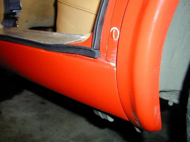
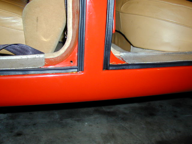
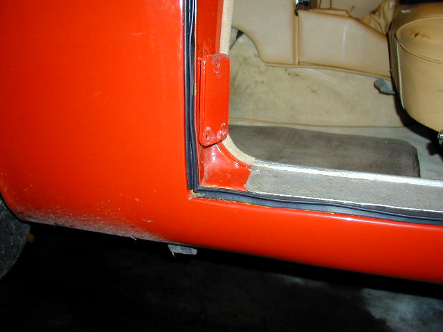
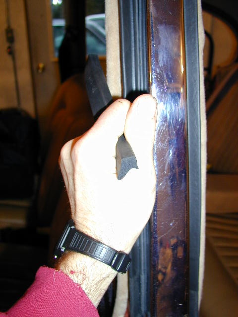
15.4 - Door Seals for a MK2/420/S-type ( Tom Carson,
March 31, 2000
)

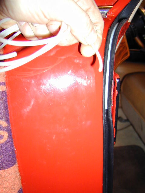
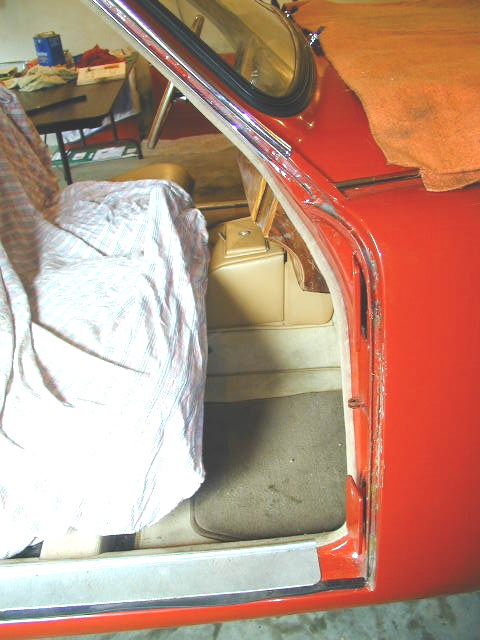
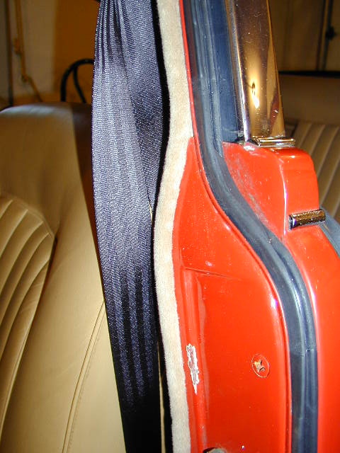
Left Side Installation
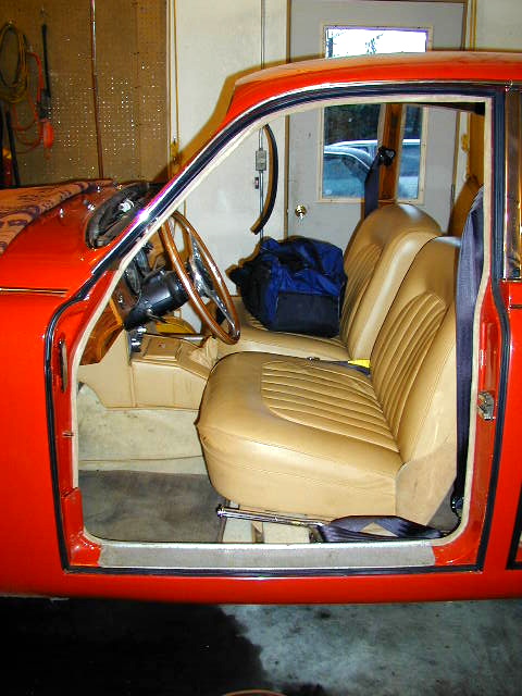
Front Lefthand Door Seals
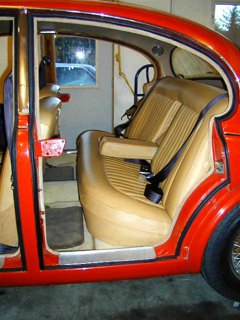
Rear Lefthand Door Seals
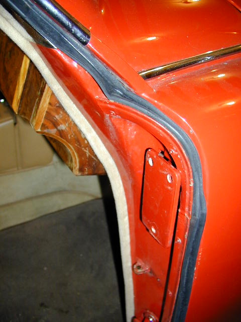
A-Post Drainage
Channel Squeezed Shut
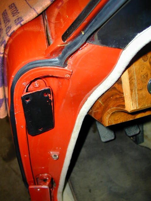
A-post drainage
route shown
A-post drainage channel
opened up with plastic tubing
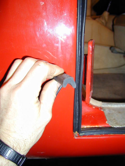
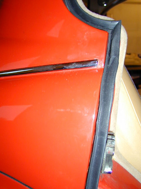
Lower A-post profile

Upper A-post profile
A-post front
channel before seal
A-post upper channel
before seal
A-post upper seal
position for max extension
of sealing surface
Sill profile orientation
Sill front righthand side
Sill rear lefthand side

Sill lefthand overview
Sill rear lefthand side
Sill lefthand B/C post
Sill front lefthand side
B-post profile
orientation

C-post profile orientation
my final decision although information varies

C-post lower
profile oreientation
B-post seal
installed
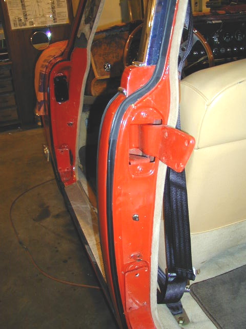
C-post seal
installed
B/C Post.
Note B-post drainage channel
to rear of seal
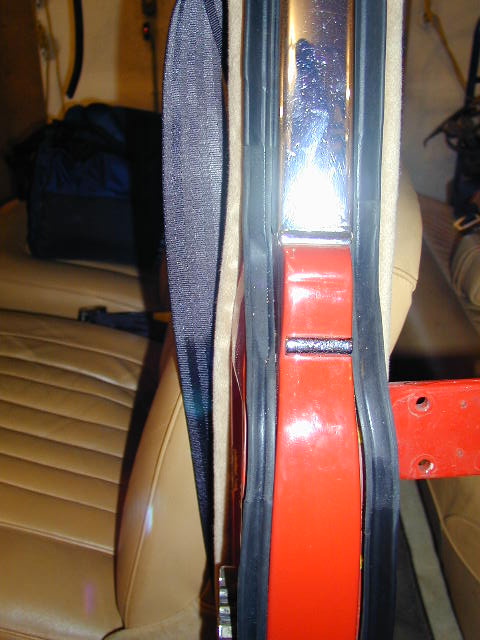
D-post righhand side. Note
drainage channel to rear

D-post righthand side,
lower section

D-post lefthand side
lower section. Note lap
for drainage
D-post righthand side looking
up from below
D-post lefthand side mid-looking to rear

Tom Carson
|
A few comments on installing door seals:
1) I have found that "super trim adhesive" (3M) does not adhere satisfactorily to the new rubber seals unless the surface of the seal to which the adhesive is applied is first roughened with sand paper and then cleaned with Acetone. If this is not done, the seals come loose within a day or so, especially if they have gotten wet in heavy rain (good old Juneau). This could be a real bummer if the seals at the leading edges of the doors come loose. I am about ready to try Super Glue as recommended by some on this list if I experience any more problems.
2) When installing the seals against which the window frames will close, take special care to position the seal so that the sealing "wing" protrudes out from the body to the maximum extent possible. This will allow the window frame to contact the seal more readily without too extreme an adjustment inside the door (at the bottom end of the frame where it bolts to the door). The factory used wooden shims at this point, I used a 1" hole saw and cut plugs out of PVC sheet material.
3) The leading edges of the rear doors were the most cantankerous seals to fit on my car. The bottom hinge would foul on the protruding "wing" of the seal. I finally trimmed the seal at that point so the hinge swung past the seal without touching it. Similarly, I found that as the door swung shut the top leading edge of the window frame would catch the protruding "wing" of the seal at the top of the "C" post. Had I left it that way, the seal would have been folded over on itself every time the door closed. Here I again slightly trimmed the seal to prevent such an occurance. This was necessary on only one side of the car.
4) The factory installed a plastic sheet on each door before the door trim panel was installed. In my opinion this is a very important item because water runs down the outside of the window, inevitably gets past the squeegee (or brush as on my doors), and finally drips off the bottom of the window mechanism on it's way to the bottom of the inside of the door. Because of the shape of the door, some of the drips actually hit the inside skin of the door first. Without that plastic carefully installed and sealed on the door skin, those drips will find their way through the various holes in the inner door skin to the inside of the car, where they will cause the carpet to get wet. Carefully installed plastic sheet keeps the water on the inside of the door. I used Sikaflex 1A urethane caulk (it is sticky, seals well, stays flexible and allows the sheet to be pulled off in the future). So long as the drain holes at the bottom of the door are functional, the water drains to the outside and the interior remains dry.
15.4.1 - Door Seal Replacement for a MK2/S-type ( Jacques B,
June 21, 2005
)
I replaced the door seals on the MK2 a couple of years ago
using J.C. Whitney Stock # ADA818835T.
The profile and consistency of these seals were a perfect
match for the still intact portions of the orginal seals I
removed.
They come in 8 ft. rolls that sell for $8.99 a piece (+
shipping). IIRC, 5 rolls were needed to do all 4 doors.
I did, however, remove the original thin rubber strip in the
bottom of the seal gutters. I don't know if it would have
been thick enough to make a difference as far as door
alignment is concerned, but the new seals ''sat'' much better
without it. In fact, I never did get around to glueing them
in, and none of them has come out yet.
15.5 - MK1 Headliner Installation ( Mike Waldron,
September 29, 2005
)
It's been ten years since I put the headliner in my MK-I, here
is what I think I remember.
First; I don't recall it being all that difficult.
Second; There are wood strips along the roof line above the
doors, attached to the body with spiral nails.
Third; The metal "spike strips" are attached with screws to the
wood strips, the teeth face the wood and are on the bottom, the screw
holes are above the teeth on the top (does that make sense?). The
headliner material "pinches" between the teeth and wood. Seems like the
teeth are angled up just a little so you can push the headliner in,
but it can not be pulled back out.
Fourth; The headliner bows go through the "pockets" sewn into
the headliner and the bow ends go into holes along the roof line
above the doors.
Fifth; The rear window seal is what holds the headliner at the
rear.
OK.
Clean hands.... trying to get dirt off the headliner once it is
installed is a pain.
Put the bows through the pockets. Not all the bows are the same,
figure out where each one goes first.
Put the bow ends into the holes.
Starting from the middle (post between front and rear doors)
push the headliner material edges between the teeth and wood.
Do a little on the drivers side then the passenger side, then
move a little forward and then a little backward. The goal
being to keep the headliner centered.
You can always go back and shove a little more in to tighten the
headliner, but you can not pull it back out! I used a putty
knife to shove the headliner material in. I pulled the excess headliner
material edge out to the door frame, then held that extra material
while pushing the headliner between the teeth and wood with the putty knife.
Keep that little "flap" of material out until you are happy with the
headliner tightness, then shove it under the teeth or trim it off.
You're going to hold onto that flap so the when you shove with the
putty knife it pulls the headliner under the teeth.
NOTE: This is the official way to do the headliner at the rear
window and will insure that the window leaks... Put the headliner out
the rear window opening, install the windows seal over the headliner
material, install the window, trim the excess material hanging out the
back of the car.
But wait!
I installed my rear window before the headliner and I just put
some weatherstrip adhesive under the window seal and used a
screwdriver to poke the headliner material under the seal and
into the glue, it's still there and the rear window doesn't leak!
Install the trim pieces.
15.6 - MK2 Headliner Removal ( Tom Carson,
October 4, 2002
)
Another trip down Memory Lane. And remember the following comments pertain
to a 1962 Mark 2.
You will be performing what the manual always calls "the reverse order" of
installation. And do this carefully so you hopefully end up with a complete
old headliner to reference when you install the new one.
Preliminary to the following steps I also recommend removing the front and
rear seats and if at all possible, the carpeting. I had glue and stuff all
over the inside of the car when headliner installation was underway.
OK, the steps for removing the old headliner:
1) remove all the wood trim pieces around the edges of the headliner (this
is not incidental, but I am assuming you know where the screws are...holler
if you don't),
2) remove sun visors, rear view mirror, and the two interior lights back by
the parcel shelf (careful when removing these last two items...there's a
wood ring each light mounts to that will probably fall to bits when you
remove it..you need the old ones for a pattern),
3) remove the front windscreen complete with rubber gasket,
4) remove rear wind screen complete with rubber gasket,
At this point you will basically be ready to begin removing the headliner
proper. Observe how it is installed. If you have a digital camera snap a
bunch of images. Now begin removing it:
5) peel the liner carefully off the lip of the rear window opening (where
you will find it glued),
6) ditto front window opening,
7) work your way along each side edge of the headliner. You'll probably
find a combination of staples, brads, glue. Note all this carefully because
you'll be there again pretty soon with the new headliner, trying to achieve
a tight, wrinkle-free installation.
8) once the front, rear, and both sides are free, you are at last ready to
remove the cants (cants are the metal bows that hold the headliner up into
position). The cants are in sleeves in the headliner, and at each end of
each cant is a metal clip that fit into a bracket welded to the inside of
the body just above the door openings.
9) starting at either the front or the rear, you will now be able to grasp
the cant through the loose fabric of the headliner and actually rotate it
back towards the center to the car and downwards. Once in this downward
"sagging" position you'll be able to lift each of those clips up and out of
the bracket. Pay particular attention here!! Each cant has it's own
particular clips. The clips are NOT interchangeable among the various
cants, and the cants are not interchangeable among the various sleeves.
Keep the digital camera at hand and proceed with care. Mark everything so
you know which cant goes in which sleeve, and which clips go with which
cant.
Once you have the cants and clips free, then the headliner is also free. I
recommend laying the old headliner out on a table or flat surface, and
installing the cants and clips back into it...and make them secure so things
don't fall apart. Keep it all together until the new headliner is ready to
be installed. Which ain't yet, by the way.
There'll undoubtedly be lots of clean-up to do. The jute matting that is
glued above the old headliner is probably history. I replaced the jute
stuff with that self adhesive "black rubber" sound-deadening mat (Dyna
Matt?) above my new headliner. It worked OK, but I made the mistake of
using every piece of the mat (it's not cheap stuff!), cutting it into small
pieces to fit here and there. I now recommend against this approach. Buy
as many mats as you need, but only install it in longitudinal pieces that
span at least two cants. Even though those mats are self adhesive (and as I
recall I also used 3M spray adhesive in an attempt to achieve maximum
overkill), I have suffered some of the smaller pieces coming loose. Not too
cool.
15.6.1 - Headliner Installation for the MKVII and MKVIIM ( Alan Schultz,
July 8, 2008
)
Picture #1 - Roof layout
Sketches A.B,& C: Sketches of how the headliner is stapled to the wooden bow follow

Picture #2: Picture of headliner for a MKIX. Same for a MKVII
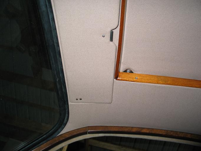
Picture #3: Headliner detail for step #19
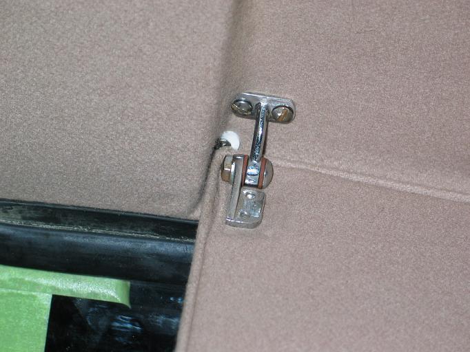
Picture #4: Sunvisor detail for step #23
|
Jaguar Headliner Installation for MKVII and MKVIIM
(May be applicable to the MKVIII, MKIX and MKX) by Alan Schultz 7/8/08
List of Materials:
1. Four (4) boxes each of medium and small size spring clips.
2. Spray can of 3M #8088 adhesive.
3. High quality sharp good cutting hand scissors.
4. Heavy Duty staple gun.
5. Box of Ľ” leg heavy duty staples.
6. Tacks similar to the ones removed when original headliner was removed.
7. Headliner materials.
8. Three or four large “C” type vise grips.
Before beginning the installation:
* This is the time to replace to rotted drain hoses for the sunroof.
It also would be best to install the new wire harness at this time (if needed).
* Check all tacking strips. They need to be in excellent condition. Replace the
strips with new plywood pieces if required.
* The nailer strip installed on the center steel bow is rubber and is very hard.
Remove it and replace with plywood or do as I did and steam bend a piece of
straight knot-free pine to conform with the steel bow’s contour.
* Add sound lining to underside of roof where desired. I used 2 coats of 3M #8088
adhesive sprayed on both the sound lining felt and the metal.
* Install the sunroof (if it was removed). The center guide rail must be bolted
to the center steel bow which will not remain accessible for long. See picture #1.
You are now ready to start installing the headliner!
1. Determine which flexible steel bow and which end of each match the mounting holes.
This is important since it determines the position of the bows when installed.
2. Insert the bows into the sleeves of the headliner
3. Offer up either bow and fasten at each end. Don’t tighten yet, leave a little play.
4. Offer up the second bow and do the same.
5. There should be excess headliner material bunched up at each end of the both bows.
Carefully cut the stitching at the ends so the bunching is eliminated. Try to snip
the same amount of stitching on each side so headliner is centered. Pull the
headliner to the sides to see if enough stitching has been cut to allow the material
to be pulled tight and sagging eliminated.
6. Now gently pull the headliner to the rear window opening. Leave the material sag
loosely. Use spring clips to hold the material at the top of the window opening.
7. Now staple the rear headliner and the front headliner to the loose wooden bow
which you should have saved after it was removed with the old headliner.
Note how it fits up to the center steel bow. Refer to the following sketches
showing the step by step procedure for completing this task.
Sketches of how the headliner is stapled to the wooden bow follow:
8. See sketch “A”. Wrap the front edge of the rear headliner material over the
loose wooden bow. Don’t staple yet. Place the wrapped bow against the center
steel bow. If there is slack pull on the fabric to tighten. Don’t pull too
hard against the two steel bows. Pull the material to the sides as well
to tighten the material. Clamp the wrapped bow to the center steel bow with
a couple vise grips.
9. Now pull the rear headliner material tighter to the rear window opening.
When the material is taunt and sag free. Place many spring clips at the
rear window opening to hold the headliner in place. Pull sides of headliner
so wrinkles disappear. If it looks good, you are ready to staple the fabric
to the wooden bow as shown in Sketch “A”.
10. Staple the fabric to the wood bow.
11. See sketch “B”. Unroll the wood bow and attach the front headliner fabric.
12. Reroll the fabric and wood bow, place on center steel bow and clamp in place.
Note: Lift front headliner material so that wood screws can be driven through
the wood bow and into the wood nailer in the center steel bow. See sketch “C”.
13. Unfasten the headliner from the rear window opening and carefully apply 3M adhesive
to the edge of the headliner. Masking areas with tape and paper to avoid spraying
areas where adhesive isn’t desired.
14. Pull headliner tight and press onto adhesive. Careful to avoid wrinkles. Put
many spring clips on the assembly and let the bond cure for several hours.
15. Picture #2 shows the rear and front headliners in place.
Picture of headliner for a MKIX. Same for a MKVII.
Pull the sides of the rear headliner to the tack strips above the rear doors
and staple. Note: I found that the 1/4” staples are only sufficient to temporarily
hold the headliner in place. In a later step, I tacked the material in place to
securely anchor the material.
16. Next is the front headliner. If your vehicle has a sunroof, the headliner will
need to be cutout for the opening. Pull the material over the opening and mark
with dressmakers marker or some such. Don’t cut on that line! Leave at least an
extra 2” of material. You don’t want to cut the opening too large and ruin headliner.
Excess material can be trimmed later.
17. You’ll need to cut at the corners of the opening to allow the material to conform
to the opening. Don’t cut too far; the material will have some stretch.
18. Pull the headliner to the sunroof opening and upwards. There should be a tacking
strip on all four sides of the opening. Staple the fabric to this tack strip.
Note: I found that the 1/4” staples are only sufficient to temporarily hold the headliner
in place. In a later step, I tacked the material in place to securely anchor the
material.
19. Work your way along both sides and staple the headliner to the tack strip above
the door and the tack strip on the sides of the sunroof opening. As you work
along check to make sure the headliner is tight and without wrinkles. See Picture #3.
20. Where the headliner is to be attached to the “A” pillar. Use a strip of double faced
tape to hold the material to the steel pillar.
21. Staple the headliner at the front of the sunroof opening.
22. Now pull the material to the front upper edge of the windscreen opening and spring
clip in place.
23. If you have recessed sunvisors, I wish you luck. I had to screw the corners of the
material in place with #4 stainless steel screws and finishing rings. See picture #4.
24. Once you are satisfied with how the front headliner looks at the “A” pillars, recessed
sunvisor pockets, the sunroof opening and the front clipped edge, you are ready to begin
using the 3M adhesive to attach the material.
25. Apply adhesive to the inside edge of the wind screen opening only and headliner fabric.
26. Stretch and stick to the inside edge of the opening. Clamp with spring clips and let cure.
27. After curing remove the spring clips and carefully trim the fabric so there is only about
an 1/8” of fabric that will fold over the windscreen lip.
28. Apply 3M adhesive to the remaining 1/8” of fabric and the outside lip of the windscreen
opening.
29. Fold over and clip in place.
30. Go back over the installation and remove any wrinkles. Try the wood trim moulding over the
doors to see if the staples and/or tacks are hidden from view. Remove those that show after
tacking the headliner in place.
Good Luck, Go Slow, Be meticulous and you’ll get a satisfactory installation,
Alan Schultz
1951 MKVII
alan@andysnet.net
15.7 - Installing MK2 rear bumper ( Greg Snow,
February 13, 2006
)
Installing MK2 rear bumper.
It is not an easy job by any means but having done it once I
realise that
the main ingredient is patience.
1. I put masking tape every where I thought the bumper may come
in contact
with the car - 2 layers in most places.
2. Install the rubber bumper to body seal on the bumper
including the
chromed metal finishers (spearpoints) if you have them. I used a
little
superglue for the finishers and also glued the last 2 -3 inches
of the seal
onto the bumper. There are supposed to be 16 spring clips to
hold the seal
onto the bumper but I didn't have them. The pressure on the seal
between the
bumper and the body is ample to hold it all in place.
3. Install the 4 rubber mounts onto the car. In the case of the
two outer
mounts, install the hat section brackets to the rubber mounts.
It is
impossible to get at the 3/4 inch bolt after it is installed.
4. Ensure that the threads are all clear of crud on both the
centre mounts
and fixing bolts and that they turn freely into the threads.
5. I had to widen the vertical slots on the centre brackets that
are welded
to the bumper 1-2 mm each side - I did not have enough lateral
movement in
the bumper to get both bolts to start without doing this.
6. Mount the 2 overriders on the bumper.
7. Ideally you need 3 people to do the job. 2 to hold it and one
to do the
bolts. My first attempt was with 2 people which would have been
OK too if
the technique had been right. Some have done it alone using
blocks etc to
support the bar. This is the least desirable option in my
opinion.
8. Offer up the bar and work on installing the 2 centre mount
bolts first.
It is a bit of a trick to get the bolt in and turning. I found
it easier to
insert the bolt with the bumper 2 inches away from the mount
then move the
bumper up nearer the mount as you attempt to get the threads
started. Here I
used a screwdriver as a lever against the head of the bolt to
keep pressure
toward the mount and a regular 3/4 inch open end spanner to get
the bolt
turning. This was the most difficult part for me as my bumper
had some
previous accident damage and the welded brackets were a little
bent. That's
why I had to ream the slots out a little I think.
9. Tighten up centre bolts most of the way but leave enough
movement in the
bar for step 10.
10. Now it is time for the 2 bolts that fix the hat section
bracket to the
bumper on each side. Here the pressure to get things fixed
whilst others are
holding the weight is off as the bar is well supported by the
centre mounts
and a little patience will get the bolts/washers and nuts
located and
turning. I have short fat fingers and found it useful to install
these
bolts/washers/nuts using long nosed pliers.
11. Once you have them all started it is a simple matter to get
the bar
sitting where it looks right and tighten up all mounting
hardware.
12. Remove the masking tape now. It is too difficult after the
next step.
13. You now need to run a tool (preferably something that will
not scratch)
along the seal to get the top flap up and sitting properly
against the body
to complete the seal.
14. Now sit back and enjoy your accomplishment with a few well
earned beers
or whatever is your poison.
|


