| ||||||||||||||||||||||||||||||||||||||
| ||||||||||||||||||||||||||||||||||||||
|
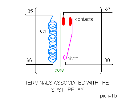
BASICS By Charlie Nowlin RELAYS II So far, In Review....... The basis for relays, is the simple electromagnet. The simplest relay, is the Single Pole, Single Throw (spst) relay. It is nothing more than an electromagnetically controlled on-off switch. This is desireable because we can now use smaller diameter wires, to control the current flow through a much larger wire, and also to limit the wear and tear on the control switch.
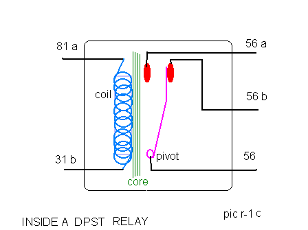
Memorizing the contact terminal numbers, and their associated components, will aid in troubleshooting. Double Pole Double Throw (DPDT) This is the relay we have all become familiar with at one time or another.
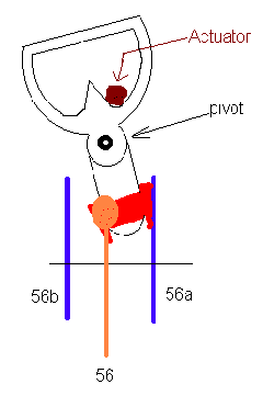
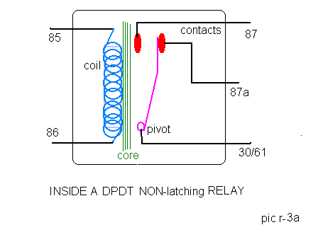
Here, we see a second set of contacts, and some different terminal numbering, 81a, and 31b, are the coil, 56 is the input terminal, 56b, is the default position, and 56a, is the coil energized contact.
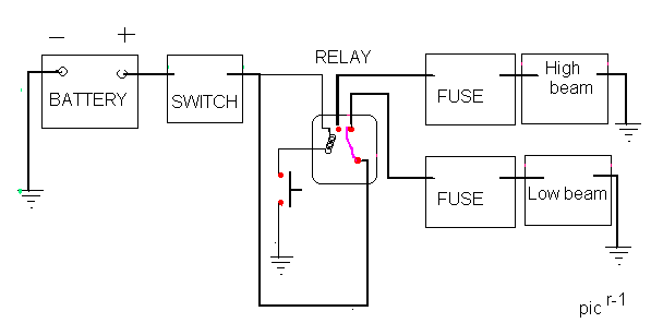
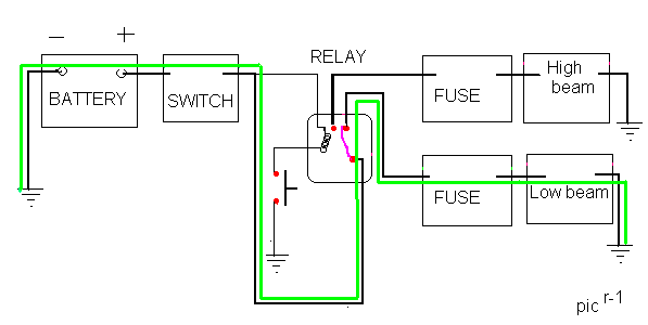
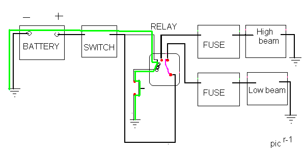
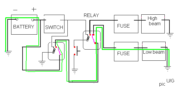
This is the wiring of the complete headlamp circuit, although simplified, showing one light for each side,..... typical in an S-III XJ6. Notice that the entire current flow for the low beams, is routed through the light switch. Not very efficient, IMHO, however it works. Upgrade available, bottom of this page
When the switch is "ON", current flows from battery, thru the fuse, to the switch, and directly through therelay's secondary contacts to the device, which in this case is the Low beams. So when ever the light is switched onthe low beams are on... Almost!! There is one other contingency......and that is the dip switch. Because the type of relay that is used in our headlight system (Jaguar) is a Latching type, it will retain the last mode used. It does not default to the primary contacts on shutdown. So it stays where it was last used. If you have used the high beams, and shut down without dipping to low, when you next turn them on they will come on in the high beam mode.
The dip switch, energizes the coil , period. The magnetic properties of the coil attract the actuator, to which the contact is connected. To understand how this works, one must visualize the working end of the relay.
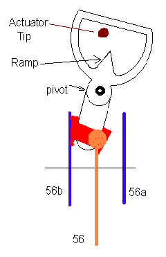
In the first pic, its default position, connects terminal 56, and 56a. The dip switch is activated. The coil is energized, the actuator tip is working against the pivot. It flips the contacts, to the new position. In the second pic, the dip switch released, terminals 56 and 56b, are in contact. The coil is de-energized, the actuator tip returns to it's rest position. The next time the dip switch is activated, the actuator will ride down the ramp, and act on the pivot in the reverse direction, ready to connect terminals 56 and 56a again.
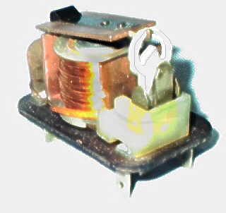
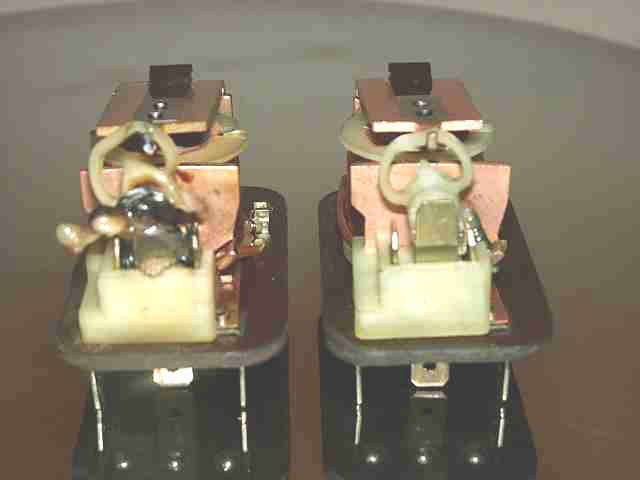
Photo of S III headlight relay, removed from within it's cover, showing the actuator, coil, contacts, and latch mechanism described above The picture below, compares the good relay (on the right), with one that had corroded/dirty contacts (left) causing high resistance on the high beam side of the circuit. This led to the production of heat, which eventually melted the mechanism.
Photo by Mark Stephenson 11/25/2000 Mark writes: TThe headlights
totally died in the '85 XJ6. A quick check of various
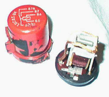
There is another type relay I will cover here. This is the start relay. The start relay is a triple pole single throw (TPST) Now before you get all shook up..... this nomenclature, if you haven't yet figured it out, is nothing more than a description of the relay, and how it works. A single pole means that there is one contact which to make contact with. Double pole means that there are two contacts. Triple pole.... you get the idea.. Now for the throws....there is single throw which means the contact can be made or broken Double throw, is either of two contacts can be made at one time. Think of it as a pendulum.It can swing in two directions, left and right, but it cannot swing both ways at the same time.So the same holds true with our relay that has a double throw. There is yet a third type of relay, found in our Jags. This is the double pole double throw (DPDT) non latching type. It's operation, is to make contact with either one contact set or the other. It, by default, does return to the preset contact when power to the coil is removed. This Relay, has a terminal marked 87a., and one marked 30/61. The "Red" relay is one such device. Until the coil is energized, the relay provides an internal path between the terminals marked 87a, and 30/61.
This type of relay is also (sometimes) used to connect an alarm system. It can also control another , or a string of relays, but that is another topic.
Upgrade
My XJ6, had a 12 gauge wire feeding the switch / relay leg. Now 12 gauge wire, is more than sufficient for two 50 watt lamps. However, I am upgrading to 7 inch H4 bulbs, and do not like the idea of all that current, running through the headlight switch. The headlamp switch contacts, are small, and have a high resistance, which means they'll get hot. With two 50 watt lamps, the current flowing through them is An addition of a 30 AMPERE $3.00 relay, will give my 17 year old switch some relief, from the increased current, and the higher resistance, and accompanying voltage drop of the small gauge wiring. You can do the same. The new relay is wired in as shown.
I have replaced all wiring to the headlights with a 10 guage wire, and also added a fused 8 gauge cable from the battery, to the area near the radiator. This will provide a high current capacity, low resistance line, for the wiring of the newer relay's I will be adding. The control circuits, have been left as is for now. Did you memorize the terminal numbers? If not, ........go back, and read again, |
|
| ||
 |
Improve your Jag-lovers experience with the Mozilla FireFox Browser!
©Jag-loversTM Ltd / JagWEBTM 1993 - 2024 All rights reserved. Jag-lovers is supported by JagWEBTM For Terms of Use and General Rules see our Disclaimer Use of the Jag-lovers logo or trademark name on sites other than Jag-lovers itself in a manner implying endorsement of commercial activities whatsoever is prohibited. Sections of this Web Site may publish members and visitors comments, opinion and photographs/images - Jag-lovers Ltd does not assume or have any responsibility or any liability for members comments or opinions, nor does it claim ownership or copyright of any material that belongs to the original poster including images. The word 'Jaguar' and the leaping cat device, whether used separately or in combination, are registered trademarks and are the property of Jaguar Cars, England. Some images may also be © Jaguar Cars. Mirroring or downloading of this site or the publication of material or any extracts therefrom in original or altered form from these pages onto other sites (including reproduction by any other Jaguar enthusiast sites) without express permission violates Jag-lovers Ltd copyright and is prohibited |
|