| ||||||||||||||||||||||||||||||||||||||
| ||||||||||||||||||||||||||||||||||||||
|
BASICS By Charlie Nowlin With special thanks to Alex Cannara. DIODES A short description A diode, is a device similar to a one way street. It will allow current to flow in one direction only, and block current flow in the reverse direction. They can be used alone, or , in configurations to allow different paths, for the current to flow. They come in different voltage / current ratings, as well as types.. This
allows engineers to build logic circuits -- the basis We will be primarily interested in testing and troubleshooting, the type found in the Jaguars. ............................................................................................................................ A diode, is composed of two regions of semiconductor (eg. silicon, germanium) A slab of semiconductor can be thought of as a resistor whose resistance depends on the amount of doping (impurities such as gallium or arsenic) that is implanted in the silicon.
They are approximately 5/16 inch long, dark grey to black in color, and have a marking band near one end to denote the cathode A semiconductor is neither a good conductor such as copper, nor an insulator (dielectric) such as glass. ............................................................................................................................ ( At the junction between the two regions, (the Cathode, and the Anode) a potential field is built-up. This field produces a barrier potential and is responsible for the (approx.) 0.7 V turn-on voltage (for silicon diodes) required in the forward direction to establish current flow. )
The schematic symbol is shown above, with it's relationship to the actual item. The junction of the actual diode, is inside and not visible TESTING the diode, is accomplished by the use of a volt/ohmmeter, set to read OHMS. For testing, one end of the diode, must be disconnected from the circuit, so as to test ONLY the diode, as other circuit components will allow for a false reading. Set the meter to the 10k ohm range, apply one test lead to one end of the diode, the other test lead to the remaining end.... It makes no difference at this point which end of the test leads goes where........ What IS important, is the relationship between the first reading and the second. So mark down the reading you first get, then switch the ends of the ohmmeter to opposite ends of the diode. Now mark down the second reading.
When a voltage is applied in the reverse direction we say that the diode is reverse biased. When the diode is reverse biased, the potential barrier builds up across the junction and opposes current flow through the diode. The greater the applied reverse voltage, the larger the barrier. When reverse biased, only a very small leakage current flows. This leakage current is called the reverse saturation current If you get the same reading, or close to the same for each of the tests, the diode is no good. You should get a big swing in the meter when you reverse the leads. It will read very low one way, and very high the other. This indicates that it is passing current in one direction (low reading) and blocking it in the other (high reading). The high reading for most all diodes should be above 1,000,000Ohms. ( 1 megohm) The low, forward
reading will in the 1-1000 Ohm range, depending on the If you have a digital meter, there is no needle to swing. You will get numerical readings. Same results apply. Putting it all together Let's follow the schematic............in steps.
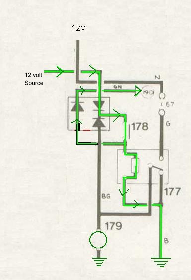
Aux. Fan relay [177] and the three diode pack STEP #1 (right) Current (green line) is supplied from a tap on the the Brake light fuse (a 12 volt source), flows thru the first diode, to the "Radiator cooling thermostat switch" [# 178] in water pump, ( when closed,) to the coil of the radiator cooling relay, energizing the coil then it flows to the common return . Current is also applied to the compressor clutch [# 190] . This operation happens when the coolant is hot.
......................................................................................................................................................
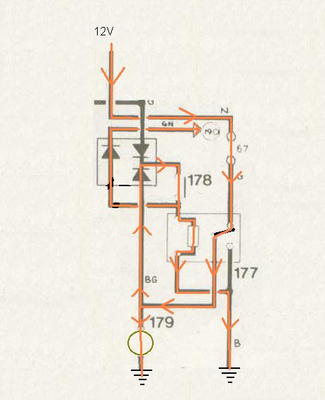
STEP #2 The coil, pulls on the actuator (of the "RED" relay on firewall ) allowing the secondary contact to close, while opening the primary contact. This allows power to come directly from the battery, (orange ) thru a fuse, to the fan, and then to the common return. The lead from the battery, through the switched contact to the fan and back through the diode to the relay coil creates a "latch", so once on, the relay stays on even when the ignition goes off. And only goes off when the thermostat (178) opens again. It will not turn on again until after the ignition is switched on. It is blocked from going to the brake switch feed by the reverse biasing of the diode in that line.
Additional Notes: One region of semiconductor within the diode is called the P region. The P region has been doped with an impurity which causes the presence of holes, or incomplete covalent bonds in the semiconductor crystal. These holes in the P region attract electrons and therefore are analogous to positive charges. Hence, the P region may be thought of as being Positive . The N region has been doped with an impurity which causes the presence of more electrons than are needed for the covalent bonds in the crystal. The ``extra" electrons (the ones not involved in covalent bonding) are available for conduction. The N region may be thought of as the Negative region due to the presence of the electrons available for conduction. Next: Hazard Switch/ Turn Signals |
|
| ||
 |
Improve your Jag-lovers experience with the Mozilla FireFox Browser!
©Jag-loversTM Ltd / JagWEBTM 1993 - 2024 All rights reserved. Jag-lovers is supported by JagWEBTM For Terms of Use and General Rules see our Disclaimer Use of the Jag-lovers logo or trademark name on sites other than Jag-lovers itself in a manner implying endorsement of commercial activities whatsoever is prohibited. Sections of this Web Site may publish members and visitors comments, opinion and photographs/images - Jag-lovers Ltd does not assume or have any responsibility or any liability for members comments or opinions, nor does it claim ownership or copyright of any material that belongs to the original poster including images. The word 'Jaguar' and the leaping cat device, whether used separately or in combination, are registered trademarks and are the property of Jaguar Cars, England. Some images may also be © Jaguar Cars. Mirroring or downloading of this site or the publication of material or any extracts therefrom in original or altered form from these pages onto other sites (including reproduction by any other Jaguar enthusiast sites) without express permission violates Jag-lovers Ltd copyright and is prohibited |
|