|
9.1.6 - Dismantle and repair blower housing ( ,
December 1, 2001
)
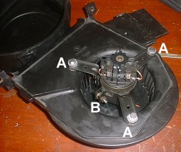
Fig. 1
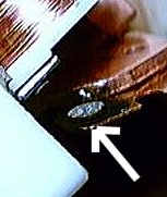
Fig. 2

Fig. 3

Fig. 4

Fig. 5
|
1. Remove 5 clips and 2 screws holding the housing together ( Haynes 10.10)
2. Pull housing apart (Haynes 10.11a)
3. Test motor with 12v. It gets dirty from the incoming air, and starts to bind up in the bearings. The dirt also causes the brushes to wear faster. Over time, the dirt and age cause the motor to bind up and blow the speed control transistor.
Undo bolts (A). See Fig 1. & Loosen clamp bolt (B) around motor to remove from housing see fig. opposite. ( Haynes 10.11b) Clean and lube the motor bearings (wd40 cleans, engine oil in each bearing for lube) and replace the brushes if necessary. (Sears hardware stores, and other places that sell power tool brushes). They may have to be filed down a bit if you cant find the exact size, but they are soft and easy to get to the correct size. (I didn't replace brushes) Also cut the wire and solder it onto the original clip as far away from the hot brush end as possible(so the solder does not melt). - ( beware of loosing spring when you slip off the cover which holds the brushes)
4. There are also two relays inside. One is isolation, the other is the high speed bypass relay. When you set the speed to low or medium, the relays connect the motor to the speed control devices. On high, the motor gets 12 volts direct. One relay gets a workout and the contacts fail. Check for continuity and power - both mine worked - but on taking the cover off the contacts on the LHS one were very badly corroded (See fig. 2.).
So needed replacing. One person used a bosch 50 amp unit ($4.95 from all electronics corp.1800-826-5432... catalog # rly-274) If that price is to high then Marlin Jones has them for $1.95, 1800-652-6733 (30 amp bosch for toyota stock # 7903-rl). Its quite hard to find one with a diode inside especially in the UK. So buy a std 40A relay from Maplin (www.maplin.co.uk) code LJ68 price ~ Ł1.30 and solder in a 1N4007 (code QL79) diode
to replace the 1N4005 that is in the existing relay. (Make sure its in the right way round)
A 1N4007 costs the same but will take 1000 volts before failing, the 1N4005 will fail above 600V.
5. Next problem is the circuit board in the housing held in by 4 rivets. This contains a NPN Darlington. (2N6284) on the inside of the housing held to the board by 2 small bolts and its two terminals soldered onto the board. One major supplier for the part is Motorola. You need to remove the Darlington from the board to check it. Use a solder sucker to free the two wires. And remove the two small bolts. To get at and check all the resistors it is necessary to drill out the rivets holding the circuit board and heat sink in place.
6. Turn the Darlington upside down, so that the two leads are facing you. Note that the leads are not centered between the two mounting holes.
The metal case is the "collector", the others are "base" and "emitter".
Verify the following:
Base Emitter Collector Reading:
Red Black approx. 8000 Ohms, or less
Black Red approx. 8000 Ohms
Red Black some resistance
Black Red open circuit
Black Red open circuit
Red Black some resistance
The reason some of the measurements are labeled "some resistance" is because you are not measuring a resistor but a diode junction which is a "non linear" device. The 8000 Ohm measurement comes from the built in resistors.
While taking the readings, do not hold the transistor in your hands. It has a very high "current gain", and your skin is conductive which could lead to a false measurement.
If the part passes all the above tests, hook up the red lead to the collector and the black lead to the emitter. You should be reading an open circuit. Dip a finger in water and touch between the metal case and the base lead (collector to base). When you do that, the Ohm-meter should read a finite resistance. The value you should get will depend on the Ohm-meter, the conductivity of your skin, and the transistor.
My readings were nothing like this - so replacement ordered from RS (UK)
Other parts include a 68 Ohm 2.5Watt resistor, a 1N5401 diode and a small glass diode, probably 1N4148 or 1N914. All these parts are easily obtained cheaply from electronic component outlets (example; in the UK Farnell Electronic Components, +113 2636311).
Blowers that won't run at low speeds almost always have a failed transistor, but replacing that alone won't always fix the fault. The resistor is there to protect the transistor from voltage spikes produced by the motor, so check the value and replace if it isn't right (most hobby multimeters have an Ohms measurement feature). The small diode feeds the blower motor voltage back to the AC computer, and has steel leads which corrode away, breaking the connection and preventing the speed control from working. They can be replaced with 1N4004 types, which are much more rugged, more easily handled, and cost just a few pennies more. These diodes are fitted with their cathodes (marked by a bar on the body) towards the transistor collector (the steel case). The 1N5401 diodes are very rugged, and unlikely to need replacing.
Some people suggest that when fitting new diodes or resistors, don't try to fit them inside the blower interior, like the originals, where they are prone to corrosion. Fit them on the solder side of the PCB (having snipped out the old parts) and then cover them with the original plastic flap using some tape.
You can fit new brushes to the blower motors, using power drill spares filed down to the right size (Kirby's tip!). But Peter has found a supplier in Seattle that supplies bushes which are are copper impregnated, have the same size pigtail,and are 5/16 x 5/16 x 5/8. So one side only has to be filed down 1/16 (REMEMBERING that you want the pigtail to come out of the side and not back or front).
Details are:
Romaine Electric (Seattle) 1-800-552-0678
Part # E93SP
Size 5/16 X 5/16 X 5/8. Copper impregnated.
Price $2.73 ea (as of Oct 2001)
|


