|
9.1 - Air con blowers ( ,
)
9.1.1 - Overview ( Martin Briscoe,
)
See warning at beginning of section 9.1 page *.
These devices contain an electronic circuit which gives speed control for all settings but "high" This comprises a Darlington transistor 2N6284, a 68 Ohm 2.5Watt resistor, a 1N5401 diode and a small glass diode, probably 1N4148 or 1N914. All these parts are easily obtained cheaply from electronic component outlets (example; in the UK Farnell Electronic Components, +113 2636311, but ask for a catalogue to get the right order numbers).
Blowers that won't run at low speeds almost always have a failed transistor, but replacing that alone won't always fix the fault. The resistor is there to protect the transistor from voltage spikes produced by the motor, so check the value and replace if it isn't right (most hobby multimeters have an Ohms measurement feature). The small diode feeds the blower motor voltage back to the AC computer, and has steel leads which corrode away, breaking the connection and preventing the speed control from working. They can be replaced with 1N4004 types, which are much more rugged, more easily handled, and cost just a few pennies more. These diodes are fitted with their cathodes (marked by a bar on the body) towards the transistor collector (the steel case). The 1N5401 diodes are very rugged, and unlikely to need replacing.
When fitting new diodes or resistors, don't try to fit them inside the blower interior, like the originals, where they are prone to corrosion. Fit them on the solder side of the PCB (having snipped out the old parts) and then cover them with the original plastic flap using some tape.
You can also fit new brushes to the blower motors, using power drill spares filed down to the right size (Kirby's tip!). Inside the blower assembly is the high speed relay, which is also prone to dirt and corrosion. Standard car accessory shop units can be used here, but check the pinout - they may not be standard.
Considering the cost of a new unit, changing the parts mentioned above gives "as new" performance at a tiny fraction of the cost.
9.1.2 - Symptoms of blower failure ( ,
)
Typically one of the blowers will fail to operate - this results in a greatly reduced amount of air coming out of the ducts, it is quite common for the poor blower to operate fine on the highest speed but not on the lower settings, or even to be on high speed at all settings this indicates that the problem is in the speed control circuitry, usualyy the darlington transistor, which is bi-passed on high speed.
9.1.3 - Air con Blower testing ( Vladam Temer,
)
The XJ40 has two blower fans in the dashboard. The blowers share some of the ducts. Unless you are quite familiar with the system, it may not become obvious when one of the blowers fails, as you will still have some air coming out on both sides of the dashboard.
The most typical blower failure is a loss of low and medium fan speeds. To test if one of the blowers is defective, follow this procedure:
1. Turn the ignition off.
2. Open the left side fuse box cover and remove the "Aircon" fuse. On the '94 MY car, this is a 20A fuse in position B4. Be very gentle with the fuse box. All the interior contacts are held in place by solder. Every time you pull out a fuse (or put it back in), you are applying force to a solder joint. Solder is not a strong alloy, so it's easy to get a cracked solder joint.
3. Start the engine. Since you removed the left side fuse, the following steps will test the right side blower.
4. Turn the blower control to "low", and listen for fan noise or feel for air out of the vents. Repeat for the medium fan speed; If "low" doesn't work, it's almost certain that medium won't work either.
5. Turn the blower control to "high". If the fan works, the most likely problem is the power transistor in the fan speed control circuit. This part is located in the blower assembly. You will have to take out the blower to do the repair.
If the fan doesn't work on "high" (as well as low and medium), check the two relays in the blower, and the fuse box. In theory, the relays can be replaced without blower removal. In practice, it may be difficult to do that unless you are quite familiar with the blower construction.
6. If none of the blower speeds work, test the 12V supply to the blower as follows:
Turn off the ignition. (Before proceeding, make sure that the right side fuse is good.) The easiest way to test the 12V supply to the blower is to get a test light with a needle in one of the leads. You can also test with any voltmeter and a needle which you will use to pierce the insulation on a wire. Locate the wires coming out of the blower. You will see two connectors. One is rectangular and white, the other is cylindrical and brown.
The cylindrical brown connector supplies 12V to the blower at all times - even when the ignition key is out of the lock. This connector has a black wire and a brown/blue wire on each end. Attach one lead of the test light to a known ground point on the car. Use the needle lead to pierce the insulation on the brown/blue wire and note if the bulb lights up. Be careful not to short out the brown wire to ground while piercing the insulation. If you do, you will be very sorry afterwards and your spouse will lose all respect for you. Remember that the brown wire always has 12V on it, even with the key out of the ignition lock.
On my car, the brown/blue wire changes color after the cylindrical connector and becomes brown without the blue stripe. It's best to pierce the wire on the blower side of the cylindrical connector. That way you are testing the connector as well. If the bulb lights up, the fuse box is probably fine. You can repeat the test with the ignition "on" and the blower on high speed. The light should still glow brightly. If you are using a voltmeter, you should do the test with the ignition "on" and the fan speed set to "high".
If the light doesn't glow, the fuse box is suspect. There is also a theoretical (but very unlikely) possibility that the black wire on the cylindrical connector got detached from chassis ground. You can test for that by getting a second needle and piercing the black wire near the blower. The light should now be connected between the brown/blue and the black wires, and it should glow.
7. If the right side blower works, repeat all of the above for the left side blower. Don't forget to put the fuse back in.
9.1.4 - Replace relays without removing blower ( ,
)
Not recommended unless you know what you are doing and that you are sure a failed relay is the problem.
From Steve Charles [s.n.charles@att.net] I have replaced the relays without removing the blowers. You can either apply vacuum to the dashpot on the bottom of the blower or hold the door open(fresh/inside air flap) and reach inside to access the relays. Don't drop it or you will have to pull the blower anyway!
9.1.5 - Remove drivers side blower and repair ( ,
)
This details my own experience but heavily quotes archived material from the modern list. Numbers in brackets refer to Haynes paragraphs.
Tools:
1. Usual selection of spanners, screwdrivers
2. 10mm socket with long extension bar (preferably thin 1/4inch type up to 14" long makes it even easier) - to reach bolts at the top of the blower holding it to the cowl.
3. Soldering iron
4. Solder sucker
5. 4 rivets and gun
6. Drill - to remove rivets
7. Duct tape (most people don't bother with this.)
8. Torch
Time:
45 - 90 mins to remove blower
30 - 45 mins to replace
Clean, repair blower and circuits allow 2 - 4 hours.
Instructions:
Note: Car can be driven without the blower in place, but refit the steering wheel and brace rods, secure and loose cables and relays, keep the fuse out. Be warned not much air will come out of the vents.
1. Disconnect -ve battery terminal - and fuse (drivers side foot well)
2. Remove plastic duct which directs air to feet.
3. Remove brace rod from steering column (10.7). 13mm spanner. Undo nuts on both ends (easier if you extend the steering wheel - as the nut nearest the steering wheel isn't easy.)
4. Disconnect vacuum line (blue) going to the shiny metal bit on the right of the housing (10.4)
5. Basically disconnect all electrical connectors in site and wd40 them. Especially disconnect electrical connectors (10.4) crossing in front of the blower. Also need to unhook the 4 coloured relays which are slotted onto a metal plate on the blower housing.
6. Remove Duct tape covering join between housing and duct to heater (10.4)
7. In the footwell of the drivers side on the left is a circuit breaker panel. Remove the front cover which you would normally do to check your fuses, but in addition remove the shroud around the fuses. This gives you ample room as you rotate the motor down and to the right.
8. Remove two bolts holding housing to cowl (10.5) The Haynes picture is very poor and I wasted a fair bit of time undoing the wrong bolt. You need a small torch. The two nuts you need are at the L and R side of the blower - right at the top pointing vertically up into the cowl. 10mm socket needed with at least 8inches of extension bar (ideally a thin one). The one next to the outside of the car is hard to see as there are a lot of wires hiding it.
Blower should now be eased down. Making sure the duct on the inside going to the heater is separated. It took me ages to get the blower down as it's a tight fit. It needs to be rotated round the steering colum and a fair bit of effort applied. I had to loosen the other steering wheel brace rod at the engine end and lowered the steering column to get the exhaust part out of the duct and around the steering column
As it comes down make sure you unplug the final two wire connectors on the inner topside.
9.1.6 - Dismantle and repair blower housing ( ,
December 1, 2001
)
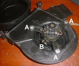
Fig. 1
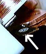
Fig. 2

Fig. 3

Fig. 4

Fig. 5
|
1. Remove 5 clips and 2 screws holding the housing together ( Haynes 10.10)
2. Pull housing apart (Haynes 10.11a)
3. Test motor with 12v. It gets dirty from the incoming air, and starts to bind up in the bearings. The dirt also causes the brushes to wear faster. Over time, the dirt and age cause the motor to bind up and blow the speed control transistor.
Undo bolts (A). See Fig 1. & Loosen clamp bolt (B) around motor to remove from housing see fig. opposite. ( Haynes 10.11b) Clean and lube the motor bearings (wd40 cleans, engine oil in each bearing for lube) and replace the brushes if necessary. (Sears hardware stores, and other places that sell power tool brushes). They may have to be filed down a bit if you cant find the exact size, but they are soft and easy to get to the correct size. (I didn't replace brushes) Also cut the wire and solder it onto the original clip as far away from the hot brush end as possible(so the solder does not melt). - ( beware of loosing spring when you slip off the cover which holds the brushes)
4. There are also two relays inside. One is isolation, the other is the high speed bypass relay. When you set the speed to low or medium, the relays connect the motor to the speed control devices. On high, the motor gets 12 volts direct. One relay gets a workout and the contacts fail. Check for continuity and power - both mine worked - but on taking the cover off the contacts on the LHS one were very badly corroded (See fig. 2.).
So needed replacing. One person used a bosch 50 amp unit ($4.95 from all electronics corp.1800-826-5432... catalog # rly-274) If that price is to high then Marlin Jones has them for $1.95, 1800-652-6733 (30 amp bosch for toyota stock # 7903-rl). Its quite hard to find one with a diode inside especially in the UK. So buy a std 40A relay from Maplin (www.maplin.co.uk) code LJ68 price ~ Ł1.30 and solder in a 1N4007 (code QL79) diode
to replace the 1N4005 that is in the existing relay. (Make sure its in the right way round)
A 1N4007 costs the same but will take 1000 volts before failing, the 1N4005 will fail above 600V.
5. Next problem is the circuit board in the housing held in by 4 rivets. This contains a NPN Darlington. (2N6284) on the inside of the housing held to the board by 2 small bolts and its two terminals soldered onto the board. One major supplier for the part is Motorola. You need to remove the Darlington from the board to check it. Use a solder sucker to free the two wires. And remove the two small bolts. To get at and check all the resistors it is necessary to drill out the rivets holding the circuit board and heat sink in place.
6. Turn the Darlington upside down, so that the two leads are facing you. Note that the leads are not centered between the two mounting holes.
The metal case is the "collector", the others are "base" and "emitter".
Verify the following:
Base Emitter Collector Reading:
Red Black approx. 8000 Ohms, or less
Black Red approx. 8000 Ohms
Red Black some resistance
Black Red open circuit
Black Red open circuit
Red Black some resistance
The reason some of the measurements are labeled "some resistance" is because you are not measuring a resistor but a diode junction which is a "non linear" device. The 8000 Ohm measurement comes from the built in resistors.
While taking the readings, do not hold the transistor in your hands. It has a very high "current gain", and your skin is conductive which could lead to a false measurement.
If the part passes all the above tests, hook up the red lead to the collector and the black lead to the emitter. You should be reading an open circuit. Dip a finger in water and touch between the metal case and the base lead (collector to base). When you do that, the Ohm-meter should read a finite resistance. The value you should get will depend on the Ohm-meter, the conductivity of your skin, and the transistor.
My readings were nothing like this - so replacement ordered from RS (UK)
Other parts include a 68 Ohm 2.5Watt resistor, a 1N5401 diode and a small glass diode, probably 1N4148 or 1N914. All these parts are easily obtained cheaply from electronic component outlets (example; in the UK Farnell Electronic Components, +113 2636311).
Blowers that won't run at low speeds almost always have a failed transistor, but replacing that alone won't always fix the fault. The resistor is there to protect the transistor from voltage spikes produced by the motor, so check the value and replace if it isn't right (most hobby multimeters have an Ohms measurement feature). The small diode feeds the blower motor voltage back to the AC computer, and has steel leads which corrode away, breaking the connection and preventing the speed control from working. They can be replaced with 1N4004 types, which are much more rugged, more easily handled, and cost just a few pennies more. These diodes are fitted with their cathodes (marked by a bar on the body) towards the transistor collector (the steel case). The 1N5401 diodes are very rugged, and unlikely to need replacing.
Some people suggest that when fitting new diodes or resistors, don't try to fit them inside the blower interior, like the originals, where they are prone to corrosion. Fit them on the solder side of the PCB (having snipped out the old parts) and then cover them with the original plastic flap using some tape.
You can fit new brushes to the blower motors, using power drill spares filed down to the right size (Kirby's tip!). But Peter has found a supplier in Seattle that supplies bushes which are are copper impregnated, have the same size pigtail,and are 5/16 x 5/16 x 5/8. So one side only has to be filed down 1/16 (REMEMBERING that you want the pigtail to come out of the side and not back or front).
Details are:
Romaine Electric (Seattle) 1-800-552-0678
Part # E93SP
Size 5/16 X 5/16 X 5/8. Copper impregnated.
Price $2.73 ea (as of Oct 2001)
9.1.7 - Re-assembly ( ,
)
Before refitting reassemble the blower housing, connect the two plugs up to the car. Refit the fuse and test to make sure its all working. (Some people have missed out this step and have had to dismantle it all again). If all is OK reassemble. Lube bolts and threads as you go.
9.1.8 - Passenger side blower removal ( ,
)
After reading Haynes and the Jag Manual, I removed as much "Stuff" as I could, Glove Compartment, Relay rack, Mounting rack for Cruise Cont ecu, Cover/Shroud around Footwell circuit breakers and also the carpet in right side.
Had a moment of panic when I started to replace all this. Should have marked some of the "Stuff" as I removed it in respect where to put it back !!!!!
For the 88,881/2 and 89 Models I would recommend especially the cover/shroud around the footwell circuit breakers. It gives you that extra inch so you do not do any damage. On passenger blower I will always remove the relay panel. Again so much better access and view of what is behind there.
One point of interest There are two ground connections I stumbled on, and one was very loose. This could have been my ground problem on my fuel pumps as I never found the ground for them.
Passenger Blower can be a real pain if you do not remove the "Stuff".
9.1.9 - Preventing problems ( ,
)
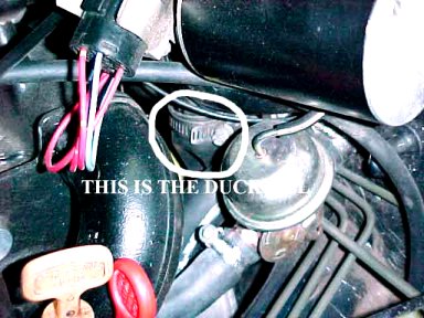
duckbill diagram
|
The blowers suck in air from the space below the grills in the cowl either side of the windscreen wiper. These grills also let rain water into this area. This water drains out below the wiper motor through a tube about 1.5inches in diameter. This tube is usually protected with a rubber 'duckbill'. You'll realise why its called this when you see it.
This design is not great as leaves and rubbish can collect in the bill and block the water from escaping. This can fill up the are under the cowl and then flow into the blower motors short circuiting their electronics, running out onto the carpet and in the worst case scenario burning out the main ECU, not funny.
So its vital to check that this draining freely, by pulling it off and cleaning. Some suggest cutting a couple of mms of the end of the duckbill to promote drainage. Others suggest leaving it off altogether. I would be wary about this a one lister reported acorns in the blower motors. I think this drain would provide a snug place for a small rodent to want to nest in, the duckbill should avoid this happening. In some models its easy to get at the duckbill from above see the picture in other people suggest crawling under the car and poking it from below (wearing goggles!).
Whilst your doing this also check the gas filler cap, this is another area that can fill with leaves and if the small drain in the rubber is blocked fill up with water above the level of the filler cap. This shouldnt be a problem but if the filler cap is loose then water will get into the gas, also not funny.
9.10 - Recirculation Flap ( ,
)
The re-circ. flap is driven by the push rod actuator. One is on left-hand side of left blower, right hand is on right hand side of right blower.
Actuator is small tin like object with push rod that extends up about 8-10 inches to push on flap arm.
Solenoid on center console (next to the "spare" one) drives both together. My pipe is pale blue. Suck opens flap. Small filter like thing in vacuum line is delay unit (read small hole).
If you get connection to solenoid wrong it will get stuck.
Solenoid either connects actuator line to vacuum or vents. If you reverse connections, vacuum in flap line won't release. And you'll also vent the vacuum supply (hisssss....)
Also realise that delay unit slow things down. Takes 30 seconds for it to move.
9.11 - Compressor Seal Replacement ( ,
)
The clutch plate has three bolt holes which you use to jack off the clutch plate. Screwing in 3 bolts will push the plate off. (All they do is hit other side of clutch so nothing would get scrunched).
Plate comes off easily. Then you have external circlip holding pulley. After removing the clip a few taps with a soft mallet allows pulley and bearing to slide off (a claw puller would be better).
Next is the electromagnet, again held on with circlip. You can get at the seals with it in place.
The shaft from the compressor sits inside a boss that protrudes to carry the pulley bearing (outside) and seals (inside). There is a small tin cap that is pried off to reveal a felt washer (lubrication). Under this is first seal.
Now it gets tricky.
The seal is held in with internal circlip. When this is out you have to get something to hook the seal out. The center (i.e. right around shaft) has a groove/ lip to take a special tool. Make a hook out of an old hose clip and gradually inch it out.
Now below this you have another seal which is fragile. It's made of a piece of hard plastic a spring, o-ring and thin steel carrier. Three prongs from the steel carrier come up from the round base, around the spring and lock onto a plastic bush. The steel base is actually keyed so it won't rotate.
It’s a snug fit so it’s hard to grip. Since you’re replacing it anyway just crack the plastic bush and pulled it out in pieces!
New seals just slide in. Make sure that the bottom seal (spring/ plastic/ metal/ o-ring) sits down in the right position so it's hole engages correctly. If not the second seal will not fit in properly and you could easily break the bottom one trying. Just inch it round till it clicks and won’t rotate further.
Second seal goes in with "extraction lip" facing outwards. The spring of the bottom seal will start compressing when you get near to correct position. At this point pop the circlip back in and push it down the last 2mm with the pliers and get the clip in.
The felt washer is next.
The Sanden seal kit has the two seals and replacement felt. Costs around $25.
Check the bearing while you’re here.
9.12 - Tip for extra cooling ( ,
)
If you set AC to manual, and you make sure that all of the "humidity" lights are out (press one and press it again to extinguish it), with low humidity this is not needed and the AC blows much colder.
|


