| ||||||||||||||||||||||||||||||||||||||
| ||||||||||||||||||||||||||||||||||||||
Jaguar V12Lucas OPUS Distributor Components (Carb)(1971-82)The Jaguar V12 was fitted with a Lucas distributor up to 1989, when the Marelli ignition system was introduced. The early cars had an OPUS ignition system, which was replaced with a Constant Energy Ignition (CEI) system in 1982; both of these systems used a Lucas distributor and both have a history of centrifugal advance seizure, but the distributors are different. The pictures on this page are of a OPUS distributor; you can also visit the CEI distributor page or look at the comparison page to note the differences. Thanks to the combination of reliable seizures and unreliable service,
not only does this distributor need overhaul but it is of some importance
that the owner of the car do it himself -- or at least directly supervise
the mechanic during the work. Hence, people unfamiliar with the Lucas
OPUS distributor will need to be taking it apart themselves. This page
provides some pictures of the parts involved to help make the job clearer.
Disassembly and reassembly is pretty easy, but there are a couple key mistakes
to avoid. One is breaking the plastic disc. See the book for tips on how to carefully remove the
plastic disk without breaking it. Robert Warnicke provided a distributor from his 1973 Series I XJ12 for
these pictures. This car has carburetors, which does make
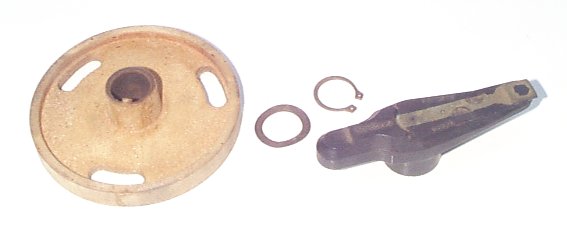
a difference here. OK, starting from the top and working downward, here are the parts installed
on the rotor carrier:
Now, even though this is a distributor from a Series I XJ12 with carbs,
that rotor is intended for the D Jetronic EFI system. It has a magnet
in the tail that operates an EFI trigger board. That's the bottom of the plastic disc; it actually has 12 little ferrite
bits embedded around the edge. For some reason, this one slid off
with no problem; many people find them seized so securely that they break
them into little bits trying to get them off. The trick is to unbolt
the entire distributor housing from the base and lift up on the housing,
using it as a puller. Here's the housing with the pickup in place: 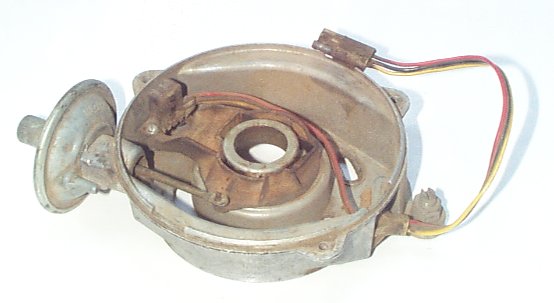
This is the part you lift to get the plastic disc off; you've got to insert a screwdriver through the three openings in the disc and remove the screws that hold this thing down, then just lift. That boss in the center contacts the plastic disc around the center and applies pulling force as uniformly as you could hope. It might still break, but you've done your best. That's a vacuum retard module; you can tell by which side the vacuum
line connects to. If it were a vacuum advance module, the vacuum line
would connect to the far side in this pic. Here's the housing with the pickup and vacuum retard module removed:
This distributor is from an XJ12 with carbs. If it was from a later
V12 with the D Jetronic EFI system, there'd be a trigger board that mounts
in here -- and there would be bosses for mounting it visible in this pic.
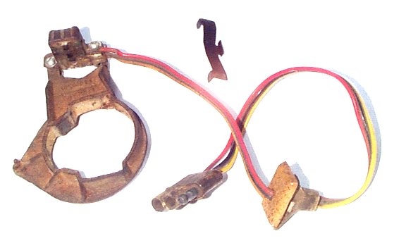
Otherwise, reportedly the components are similar. Here's the pickup and the phenolic swivel plate that holds it:
That's the OPUS pickup. It's a transformer with an E-shaped core
and one input and two output coils. A 600 KHz signal is sent to the
input coil, and the output of the two output coils are wired against each
other and normally cancel each other out. However, when one of the
ferrite inserts in the plastic disc lines up with one side of the E, it
makes one coil's output stronger than the other and a net output signal
is generated. The amplifier picks up that signal and triggers a spark. The spring clip at top center of the picture retains the swivel plate to
the housing, and also holds it preloaded against one side of the boss it's
attached to. This helps minimize slop and hysteresis in the advance
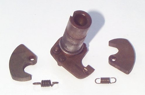
curve. Next, the rotor carrier shaft and the centrifugal advance weights and springs:
Yes, the two springs are supposed to be different. I have no idea
why, but everyone who gets into a distributor thinks they're supposed to
be the same and that someone musta screwed something up in here. The
thicker spring has an elongated loop on one end which allows the advance
to move a bit under the influence of the thinner spring only. After
the slack is taken up, further advance stretches both springs. This
is what provides the "knee" in the advance curve. By the way, either
spring will fit on either side of the assembly, and in doesn't matter which
end of either spring goes where. The rotor carrier shaft itself is held onto the distributor shaft with
a screw down inside that center hole. There's a felt plug that must
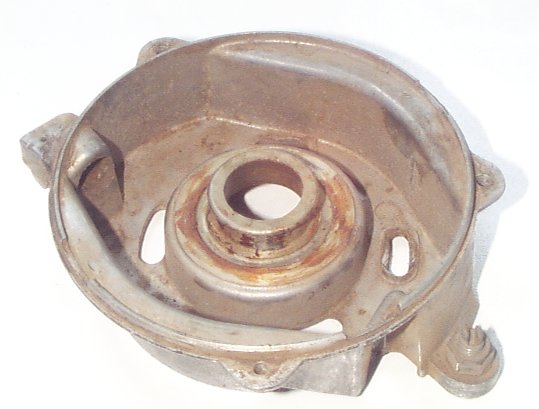
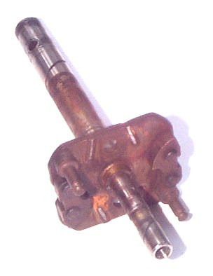
be pulled out to get at it. Getting down to the nether regions of the distributor, this is the shaft
itself:
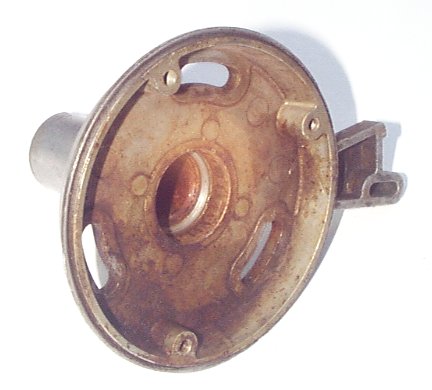
The shaft gets installed in this base:
There are three parts that are installed on the shaft as it's installed
in this base:
Did I say three parts? Yes, I did; there's also a seal, but the seal
in this distributor fell out in pieces and there wasn't much point to taking
a picture of the little black chunks. Too bad, too, because the seal is a key issue. It installs in a very
narrow shelf within the housing, the only area that looks clean in the pic
above. Word has it that this seal is unobtainable. If you actually
want to keep crankcase vapors out of your distributor (and, trust me on this,
you most definitely do want to keep the crankcase vapors out of your
distributor!) you will need to take that base to a machine shop and have
it machined to fit a commonly-available seal. You'll also want to use
a Viton seal if you can find one so it doesn't end up in chunks like this
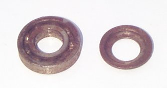
one did. That washer is cup-shaped just to permit it to sit properly on the shaft
under the plate that holds the centrifugal advance parts. It spaces
the bearing on the shaft. There is some question about the order of assembly of these parts. Is
the bearing press fit onto the shaft, or is it press fit into the housing?
It's difficult to be pressed into both, because that would mean that
the only way to assemble the parts would be to press the bearing onto the
shaft and then drive the shaft/bearing assembly into the housing, which
would apply pressing force through the bearing rollers. Ungood. You
might base your decision on trial fit; if the bearing needs to be pressed
onto the shaft, then do that first; if, on the other hand, the bearing will
slip onto the shaft, then press the bearing into the housing first. If
it seems tight on both, you might press the bearing onto the shaft first,
then freeze the bearing/shaft assembly while heating the aluminum base (being
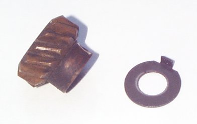
careful not to damage the seal!) prior to assembling them. On the bottom end of the shaft there is a flat thrust washer and a gear
held on by a pin:
The thrust washer has a little tang to make sure it doesn't rotate against
the aluminum base. That gear is solid brass. There is a sleeve bushing in the housing just above the thrust washer.
Hence, the distributor shaft is supported by a sleeve bushing and
a ball bearing with a seal in between. Hence, the sleeve bushing --
which handles the radial load caused by that gear mesh -- is lubed by the
oil splashing around inside the crankcase (and a scroll groove on the shaft)
while the ball bearing runs dry. The bearing therefore needs to be
lubricated during installation, or by dribbling oil down into the distributor
and hoping it gets there. Note that the bearing shown above has no dust covers or seals on it. Basically,
anything flopping around inside the distributor can get into that bearing.
That may indicate that oil applied to the distributor rotor shaft
(soaked into the felt) is intended to work its way into this bearing. But
it also means that any dust or grit are going to take their toll on that
bearing. If you're replacing the bearing anyway, you might opt to choose a bearing
with dust seals. Dust seals will still normally allow oil to leak
in, but will keep chunks out. Alternatively, you might consider a bearing with actual seals on it --
and then just omit the seal under the bearing. You could opt for a
bearing with a seal only on the top side, which would allow the bearing itself
to get some lubrication from the crankcase. |
|
| ||
 |
Improve your Jag-lovers experience with the Mozilla FireFox Browser!
©Jag-loversTM Ltd / JagWEBTM 1993 - 2024 All rights reserved. Jag-lovers is supported by JagWEBTM For Terms of Use and General Rules see our Disclaimer Use of the Jag-lovers logo or trademark name on sites other than Jag-lovers itself in a manner implying endorsement of commercial activities whatsoever is prohibited. Sections of this Web Site may publish members and visitors comments, opinion and photographs/images - Jag-lovers Ltd does not assume or have any responsibility or any liability for members comments or opinions, nor does it claim ownership or copyright of any material that belongs to the original poster including images. The word 'Jaguar' and the leaping cat device, whether used separately or in combination, are registered trademarks and are the property of Jaguar Cars, England. Some images may also be © Jaguar Cars. Mirroring or downloading of this site or the publication of material or any extracts therefrom in original or altered form from these pages onto other sites (including reproduction by any other Jaguar enthusiast sites) without express permission violates Jag-lovers Ltd copyright and is prohibited |
|