| ||||||||||||||||||||||||||||||||||||||
| ||||||||||||||||||||||||||||||||||||||
Jaguar V12Lucas CEI Distributor Components(1982-89)The Jaguar V12 was fitted with a Lucas distributor up to 1989, when the Marelli ignition system was introduced. The early cars had an OPUS ignition system, which was replaced with a Constant Energy Ignition (CEI) system in 1982; both of these systems used a Lucas distributor and both have a history of centrifugal advance seizure, but the distributors are different. The pictures on this page are of a CEI distributor; you can also visit the OPUS distributor page or look at the comparison page to note the differences. The combination of reliable seizures and unreliable service means that
not only does this thing need an overhaul, but it's of some importance that
the owner of the car do it himself -- or at least directly supervise the mechanic
during the work. Since people unfamiliar with the Lucas CEI distributor
will need to be taking it apart, this page provides some pictures of the
parts involved to help make the job clearer. Disassembly and reassembly
is pretty easy, but there are a couple key mistakes to avoid. One is
stretching the centrifugal advance springs, only too easy to do. See
the book for tips on how to carefully remove the
rotor and the star wheel without stretching the springs. This is what the base and shaft of the Lucas CEI distributor looks like with almost everything else removed: 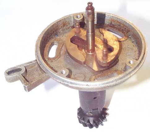
This assembly was not disassembled any farther than this while preparing
these pictures, so there are no pictures here of the bearing, seal, shaft,
etc. It is believed they are similar to those in the OPUS distributor,
so you can look at the OPUS page where
pictures are provided. Note that the ball bearing is a press fit into
the base on the OPUS but reportedly is secured into a larger hole in the
CEI base with a wrinkled collar to hold it centered. Also, I think
the gear on this CEI is steel, while the early OPUS units had a brass gear.
Note the centrifugal weights in place on their pivots. Also note the configuration of the slender upper portion of the shaft itself. This is where the rotor carrier shaft is installed, and an infamous nylon clip is snapped onto that little knob at the top end. As described in the book, a tiny O-ring and a small washer or two or even a suitable generic press-on spring steel clip can be used in place of the nylon clip. Here's what the rotor carrier shaft itself looks like: 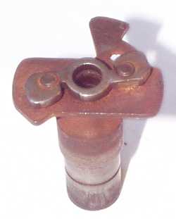
The symmetrical "propellor-shaped" plate attached to the bottom end of
the pins is a cam that is contacted by the centrifugal weights themselves.
The tang hanging off one side of the base plate (top of the picture at left)
is a stop that limits the total advance provided at high RPM; the pivot
pin on one of the centrifugal weights hits the side of this tang.
The keyway aligns both the star wheel and the rotor. The snap groove
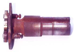
is where the C-clip fits that retains the star wheel. On the CEI distributor, there is a "thingy" that serves as a thrust washer at the bottom of the rotor carrier shaft, and it looks like this: 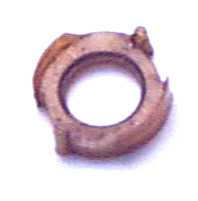
I'm sorry, but the camera I'm using isn't good at closeups, and this part is only 1/2" OD. It's clearly more than a simple thrust washer. The two pins (1 o'clock and 7 o'clock in this picture) are provided to locate the thingy relative to the cam plate on the bottom of the shaft in order to ensure that the recesses in the side of the thingy (immediately clockwise of the pins) are located properly to allow an arm on the centrifugal weights to swing past without interference. The paper-thin lips (4 o'clock and 10 o'clock) apparently serve as an inner stop for the centrifugal weights, preventing them from making a metallic noise when they move to the fully retarded position (idle or below). The thingy is not only NLA, it never was available. Lucas didn't see fit to include a replacement in their distributor rebuild kits. In fact, it's called a "thingy" because nobody even knows what Lucas called the part! If you happen to have an intact thingy, it is a little bit too easy to install it incorrectly. There is an illustration in the book showing proper installation. Here's a photo of the thingy sitting properly located on the rotor carrier shaft: 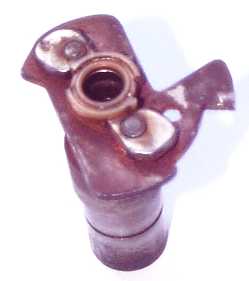
Note the location of the pins in the notches on the cam plate. The recesses in the side of the thingy do not line up with the "wings" of the cam plate, but rather are located where an arm on a centrifugal weight swings by with very little clearance. Being both a Lucas part and a British nonmetallic part, it's only too likely that your thingy is not intact. Fortunately, it can be functionally replaced with a simple bronze thrust washer, as described in the book. Every now and then, an alarmed owner writes to the xj-s list to report that his distributor had two different springs in it, obviously someone has been fiddling around and put the wrong parts in there, where can I obtain the correct springs? I'm not sure where the idea that the two springs need to be the same comes from, but to put the issue to rest: the springs are supposed to be different. 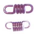
Note that the thinner spring snaps securely onto the pins on the distributor
shaft and rotor carrier shaft, but the elongated loop on one end of the thicker
spring is provided to allow the advance to move a ways before even engaging
this spring. This is how the "break" in the advance curve is provided;
up to a certain RPM, only the thin spring is involved and the advance curve
is fairly steep. After the "break point" is reached, the thick spring
engages, and the advance curve is much flatter from then on. At an
even higher RPM, a pin contacts the tang on the rotor carrier shaft base
plate, and the advance mechanism is locked at that point from there on up,
no further centrifugal advance is possible. The mechanic going deeper into the distributor may compound the problem
trying to get the iron star wheel off. It is often stuck as well, and
simply pulling will overpower the nylon clip and stretch the springs. It
is important to be holding the rotor carrier down with a thumb in the center
while pulling up on the iron star wheel to remove it. The thinner spring with more coils can be stretched all over the place
without any permanent damage, but the thicker spring with fewer coils is
easily stretched to the point of distortion. If the correct length is
known, it is also a fairly simple matter to compress it back to a shorter
free length; just put it lengthwise between the jaws of a pair of pliers and
squeeze. I would love to be able to provide a specification for what
the overall length is supposed to be, but unfortunately do not have a reliable
source for such data -- for all anyone knows, their spring has been stretched
during a previous overhaul or while they were taking it out themselves. |
|
| ||
 |
Improve your Jag-lovers experience with the Mozilla FireFox Browser!
©Jag-loversTM Ltd / JagWEBTM 1993 - 2024 All rights reserved. Jag-lovers is supported by JagWEBTM For Terms of Use and General Rules see our Disclaimer Use of the Jag-lovers logo or trademark name on sites other than Jag-lovers itself in a manner implying endorsement of commercial activities whatsoever is prohibited. Sections of this Web Site may publish members and visitors comments, opinion and photographs/images - Jag-lovers Ltd does not assume or have any responsibility or any liability for members comments or opinions, nor does it claim ownership or copyright of any material that belongs to the original poster including images. The word 'Jaguar' and the leaping cat device, whether used separately or in combination, are registered trademarks and are the property of Jaguar Cars, England. Some images may also be © Jaguar Cars. Mirroring or downloading of this site or the publication of material or any extracts therefrom in original or altered form from these pages onto other sites (including reproduction by any other Jaguar enthusiast sites) without express permission violates Jag-lovers Ltd copyright and is prohibited |
|

