| ||||||||||||||||||||||||||||||||||||||
| ||||||||||||||||||||||||||||||||||||||
Jaguar V12H.E. - 'A' & 'C' EmissionVacuum Advance Components
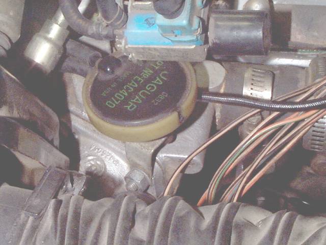
Note that a vacuum regulator was added to the 'A' and 'C' Emission scheme for 1983, similar to (but not the same as) the regulator that had been included in the 'B' Emission scheme (UK and Europe) earlier. Unfortunately, the 'A' and 'C' scheme with the regulator didn't make it into the ©1982 Supplement. If your US-spec car has the regulator but your copy of the Supplement does not, you need to either find a copy of the later edition Supplement A (page 17-4) or a Haynes manual (Fig. 13.32). Note that the electrical schematic shown on page 86-25 of the ©1982 Supplement and later Supplement A does not apply to this system. That schematic is only valid for the 'B' Emission scheme (UK and Europe). All the repair manuals show only schematics and descriptions. The Electrical Guide, Publication S57, actually shows pretty good drawings of parts and indications of their locations. The Jaguar Parts Catalogue also shows fairly good illustrations. But for some people, a photo is worth a thousand words, so here are some photos. First is the dump valve, item E in the schematics; it's "PT No EAC4070" in this picture.
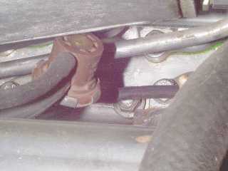
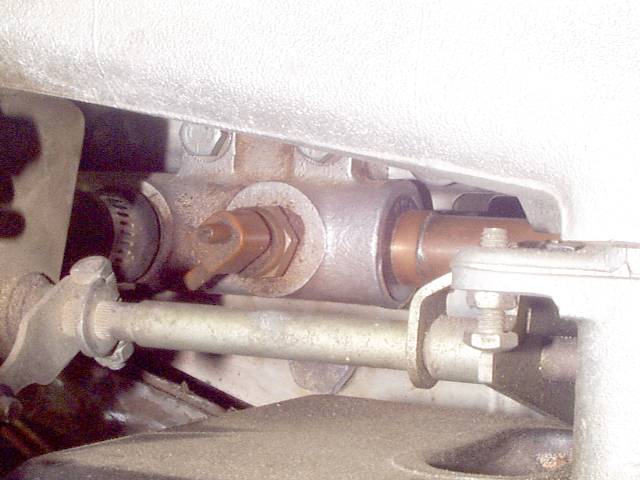
This device is bolted to the right side thermostat housing. Note that it is actually mounted upside down from the orientation indicated in the schematics, so talk of "top" or "bottom" is bound to cause confusion. The connections matter; the connection near the flat side must be connected to the port on the bottom of the butterfly housing, about a half inch inward from the butterfly edge when closed. The butterfly edge therefore passes over this port at about half throttle. The connection away from the flat side is teed into the line to the vacuum advance capsule itself. The light blue thing at the top center is the result of a recall on the cruise control system. It is a redundant control valve assembly, designed to shut off vacuum to the cruise control actuator even when the solenoids within the actuator fail. The plastic duct in the foreground is Kirby Palm's cold air intake modification; an unmodified car will have the trumpet on the front of the right air filter housing in this location. Next is the vacuum regulator, item C1 in the later schematics that show it at all.
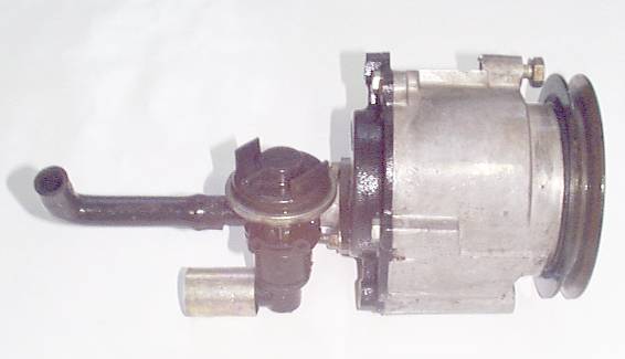
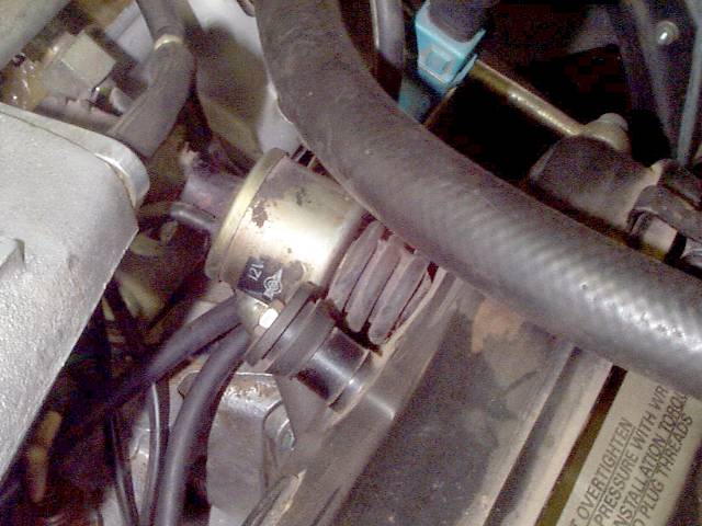
There are three hoses connected to this thing; the one on the other side is not visible in this picture. This regulator just hangs from the hoses underneath the right side intake manifold. This picture is of Palm's '83, and his regulator has been removed and later reinstalled so it may not be exactly where it appears in unmodified cars. It doesn't really matter where it is, as long as it doesn't get tangled up in the throttle linkage or anything. The Air Switch Valve or Air Switching Valve, item T on the diagrams, is on the back end of the air pump.
The hose at the left connects to a short pipe which leads to a grommet that plugs into the right side air filter housing. The shiny cylinder at the bottom is a fitting that connects to a metal pipe that leads to the air rails that direct pumped air into the exhaust ports. This fitting is in line with the pivot bolt on the bottom of the pump so that the belt can be adjusted by moving the pump around this pivot without disturbing the metal pipe.
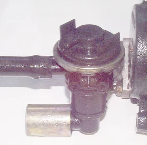
The Air Switch Valve determines whether the air being pumped gets injected into the exhaust ports or simply gets wasted into the right side air filter housing. This doesn't sound like part of the vacuum advance scheme, but it appears on the same diagram in the books so it makes sense to include it here. The "Thermal Valve", item S in the diagrams, is what controls the Air Switch Valve. This item is screwed into the right rear coolant manifold, which puts it under the throttle linkage on the right side.
This particular pic is of Kirby Palm's car, and obviously this item is no longer connected; you'll note that the pix of the air pump were taken on a white background. The Thermal Valve plugs the hole nicely, though, so it stays. Also note in this picture that the original rusty coolant pipe has been replaced with a copper pipe, as described in the Book. The solenoid air switch, item H in the diagrams, is also known as the supplemental air valve. It's attached to the inboard side of the front end of the RH air filter housing.
It's simply unbelievable how much confusion is involved in the two names for this part; see the solenoid air switch page on the issue. That page also includes an idea for replacing it with a better part from a Toyota. The solenoid air switch raises the idle to compensate for the solenoid vacuum valve killing it, so if you remove the solenoid vacuum valve you could go ahead and remove this -- but you might choose to keep it. The day your Auxiliary Air Valve gives up the ghost, you'll wish you had kept it! And of course, you'll want to keep the 45-second timer to operate it, unless you come up with another method of control. This page should include pictures of the solenoid vacuum valve and the 45-second timer/relay, but niether of those things exist on Palm's car. If anyone wishes to submit suitable photos, they will be included here. Off the record: Palm recommends that the vacuum regulator and the dump valve be maintained in these cars, regardless of emission regulations or desires of simplicity; the vacuum regulator is simply a good idea, and the dump valve is necessary to keep it from becoming a bad idea. The regulator allows a controlled amount of vacuum advance at idle; without it, your choices are no vacuum advance (works fine, but less efficient and generates more waste heat at idle; also results in a sudden power surge coming off of idle as full vacuum is applied) or full vacuum advance (which can result in an unstable idle; this is the system used in the pre-regulator US-spec 1982 models). The dump valve allows the vacuum to be dumped quickly when the throttle is suddenly floored; if it had to bleed off through the vacuum regulator, it'd take too long and the engine would detonate briefly just when you'd really prefer it didn't. The solenoid vacuum valve and 45-second timer/relay are there to help light off the catalytic convertors on startup, and therefore are important to maintain EPA emissions status -- but they really don't hurt anything, you might as well leave them alone. Unless you don't have catalytic convertors, in which case they are completely worthless. If you have doubts about the proper functioning of any of these components, you can connect full vacuum advance straight from the rear of the right side intake manifold directly to the vacuum advance capsule, and leave everything else out of the circuit. The car should run just fine, aside from the idle being a little faster than normal and perhaps a little unstable. This serves as a good test, confirming whether problems are from this system or from elsewhere. If you can get away with it, removal of the air pump is always a good idea. It represents a horsepower drag on the engine at all times. On any car with oxygen sensors, it only feeds air into the exhaust ports while the engine is cold; once warmed up, it must be wasted for the oxygen sensors to provide correct data to the EFI system on fuel mixture -- a bunch of additional oxygen being pumped in would obviously screw things up. The air injection system, even when in place, is usually non-functional due to the passages in the head getting totally plugged with carbon; this system was evidently designed to only work long enough to pass the EPA qualification tests. As long as your local emissions tests are done with the car warm, this air pump won't make any difference. Of course, if the inspector goes looking for an air pump under your hood and doesn't find one, that would be trouble. Note, however, that the air pump also serves as the adjuster for the A/C compressor belt, so you'll need to replace it with something -- an idler pulley or a GM alternator are popular choices. Even if you must keep the air pump, you should definitely relocate the waste air connection. It connects to the wrong side of the air filter housing, the engine side, so it pumps unfiltered air into the engine. It has also been known to chuck its guts into the engine. Either waste the air overboard, or at least reconnect it to the other side of the air filter housing. |
|
| ||
 |
Improve your Jag-lovers experience with the Mozilla FireFox Browser!
©Jag-loversTM Ltd / JagWEBTM 1993 - 2024 All rights reserved. Jag-lovers is supported by JagWEBTM For Terms of Use and General Rules see our Disclaimer Use of the Jag-lovers logo or trademark name on sites other than Jag-lovers itself in a manner implying endorsement of commercial activities whatsoever is prohibited. Sections of this Web Site may publish members and visitors comments, opinion and photographs/images - Jag-lovers Ltd does not assume or have any responsibility or any liability for members comments or opinions, nor does it claim ownership or copyright of any material that belongs to the original poster including images. The word 'Jaguar' and the leaping cat device, whether used separately or in combination, are registered trademarks and are the property of Jaguar Cars, England. Some images may also be © Jaguar Cars. Mirroring or downloading of this site or the publication of material or any extracts therefrom in original or altered form from these pages onto other sites (including reproduction by any other Jaguar enthusiast sites) without express permission violates Jag-lovers Ltd copyright and is prohibited |
|