|
7 - Wheels, Suspension and Brakes ( ,
)
7.1 - Hydraulic System ( ,
)
XJ40 Hydraulics, System Test :
Initial test :
Required equipment:Stopwatch, tape measure, and strong right leg!
Check Ride Leveling Struts :
Measure height at rear fenderwell Run car above idle, check and measure rise Run at idle, check and measure rise, 5/8" is factory recommended maximum. Use 1/2" as a safety standard. Gas bladder in strut is ruptured if rise is excessive. Strut pair needs to be replaced or converted.
Check Accumulator :
Run car at 2000+ RPM for 30 seconds. Shut motor off and turn key on to activate VCM. Pump pedal slowly, 3 count intervals, check the number of times before the low brake pressure warning light comes on. A fully charged accumulator will go 9 pumps. 4 pumps necessitates system check out, probable accumulator bladder failure.
Check Charge Solenoid :
Continue pumping down system after previous test until pedal is rock hard. Start car and stopwatch, run at idle, observe VCM. Stop timer when low brake pressure indicator goes out. A red border can be seen if a different warning is reading on the inner screen. The red border is a background indicator of this warning. Test several times. 9 to 15 seconds is a good reading. Any longer and pump pressure could be low or charge (load) solenoid may not be seating. Common probable fault is the charge solenoid.
Pump, Charge Solenoid, Accumulator Combo Test :
Run car at 2000+ RPM for 30 seconds. Return to idle. Pump brake pedal firmly and swiftly until low brake pressure light comes on. Stop at 30 pumps. Roughly 10 pumps usually signals a faulty charge solenoid (not seating). It is less likely but possible for low pump pressure or a completely discharged accumulator to fail this test. See pump test.
Hydraulic Pump Test :
Disconnect line to valve block. Check pressure. Most failed pumps can be stopped off with thumb pressure. Check flow of ??? per minute???
Check Valve Test :
To check discharge of hydraulic ride leveling system, charge system and measure ride height at fender lip. Recheck height after 12 hours. More than 1/8"??? sag is a sign of a faulty check valve located behind the up solenoid.
7.1.1 - Brake Accumulator Replacement ( ,
)
The replacement of the accumulator on the 3.6 litre XJ40 can be very easy or very difficult - just the luck of the draw. It is absolutely essential to completely depressurise the system before attempting this replacement, as releasing high pressure oil can be very dangerous.
If the entire accumulator assembly is removed from the car, the only hard part is getting the hydraulic connections back on and not cross-threaded. Make a clear note of how far the connections screwed in, to be certain if they are cross threaded or not on replacement before using a spanner. Also, if the clamp around the accumulator (that holds the assembly on the car) is attached but left loose until the connections are almost fully tightened, it can make the job easier.
Another caution is in unscrewing the old accumulator from the aluminium block and screwing on the new one. Using a spanner is not a good idea. It is much better to clamp very lightly in a vice with wood blocks and use a filter wrench. The accumulator does not need to be over tightened. It seals with an 'O' ring and cannot undo when in place.
Some mention has been made of the electrical block connectors. Having fiddled with these on several occasions, they are very simple to dismantle after the first time. The pins each have a small nib that springs outward when the pins are in place and stops them from pushing back. After fishing out the seals from inside the plug, this nib is accessible and can be bent back in with a very small screwdriver or similar. Before re-assembling, it is necessary to bend them back out.
7.1.2 - Accumulator Non Return Valve ( ,
)
The seats for the valves may eventually a number of ridges worn in to them reducing the length of time they hold pressure for. Jaguar don't sell the valve except as part of the switch housing assembly. These ridges can be removed with wet or dry paper, finishing off with 1200grit.
The alloy block that the Accumulator vessel and charge/ pressure switches screw into has two pipes also screwed into it. The top pipe (from the booster) screws straight into the block. The bottom pipe (from the Valve Block) screws into what looks like a 22mm nut. If this is removed a small spring loaded plunger is revealed. This seats against the inner face of the 22mm nut. It was this inner face that needs cleaned up.
You may need to remove the whole assembly and get the block in a vice as the 22mm is quite tight.
7.1.3 - Self-Leveling Suspension ( ,
)
The best answer here is if you have ANY problems, replace them with non-self leveling shocks. Jaguar do a conversion kit, the following is a summary of the Jaguar Technical Bulletin and does not cover removal/ replacement on the car itself.
Having removed the assembly from the car dismantle it and rebuild the new units. Iĺm assuming any kit will have fairly detailed instructions on this.
Not forgetting to grease everything reassemble and tighten top nut to 23-28 ft-lb.
Remove luggage compartment front trim panel and find the rear axle electrical connector. ( ĺ92 black 8 way, Ĺ93 white 8 way connector)
Remove the following wires:
Pin -ĺ92 Ĺ93
1
brown/ blue
brown/ orange
2
white/ slate
white/ slate
5
yellow/ brown
yellow/ orange
6
yellow/ blue
yellow/ blue
Tape up the wires. DO NOT remove the brake pad sensor wires.
Refit trim.
Jack up vehicle and remove self leveling struts.
Remove hydraulic crossover pipe from clips above rear subframe.
Install new assemblies.
Find valve block, (-ĺ92 on right hand inner wing, Ĺ93 under front crush tube).
Disconnect rear suspension feed pipe from block.
Plug with bleed screw (part no. CAC 8293) and tighten to 12-14 ft-lb.
Remove feed pipe from body clips.
Start engine and check valve block for leaks.
Jaguar official repair time 2 Hrs.
7.15 - Steering ( ,
)
7.15.1 - Steering Racks ( ,
)
Steering Racks (rebuilt exchange) should take less than 45 minutes to change. Add 15 more minutes to readjust the toe (if you measured the exact distance between tie rod ends and between one tie rod end and a chassis part (to establish the same steering wheel position you had before) prior to removing the old rack and you'll come in at just under an hour.
7.15.2 - Power Steering Leaks ( ,
)
The most likely source of a leak is the hose that feeds the pump. Thatĺs the first thing that goes. There is also an oil passage running to the head that leaks above the pump, and engine oil will dribble down onto the pump.
The power steering pump itself can also leak. The leak typically comes from an O-Ring inside the pump towards the back of the car.
The high pressure line comes from the back of the pump. There is a small O ring on the high pressure line fitting this may be the source but..
The high pressure line is threaded into what looks like a bushing. Be careful when you remove the bushing as a spring loaded piston may pop out. On the "bushing" is another O ring that may leak.
Approx. 30 minutes work.
7.2 - Brake Switches ( ,
)
If there seems to be oil dripping out of the wire end of either switch attached to the accumulator the switch needs to be replaced. They are not cheap and they are two different switches so make sure you get the right one.
7.20 - Front Suspension Replacement ( ,
)
With the suspension jacked up remove the top nut. (see below) then lower the suspension and the weight of the lower suspension and spring pressure will pull the shock down. The shock tends to extend itself as you lower the suspension so you will need to reach under the mudguard and compress it a little by hand to get the top stud clear. It may be worth replacing the lower shock mount (metalastik bush) but it is difficult to remove and replace in situ without a proper tool.
The official Jaguar Tool is a long and strong bolt with the appropriate adapters to allow winding out the old bush and winding in the new.
An extended socket might help but the problem is that, once you have loosened the nut the first half turn or so, the body of the shock turns as you turn the nut due to the nut being a 'Nyloc'. Thus there are flats on the top of the stud that take a spanner to stop this turning. This means that you need an open ended on the nut to hold it while you turn the top of the stud - or vice versa.
7.21 - Wheel Bearings ( Pete Crosby,
December 15, 2001
)
Here are the bearing and race numbers and they should fit any 1987-1989 XJ40. I don't know if they are the same for later cars. Someone with a complete parts list could check and see if the Jaguar part numbers are the same for all years. These are TIMKEN numbers:
Outer bearing: L45449
Outer race: L45410
Inner Bearing: L68149
Inner race: L68111
7.21.1 - Wheel Bearing Packing ( Al Diamant,
December 15, 2001
)
Both front and rear bearings should be cleaned and regreased at 100,000 miles at least, however itĺs worth doing more often.
A dangerous practice is to clean the old bearings in gasoline. It does work well, but I have seen too many accidental explosions. The bearing should have two baths. AVOID THE TENDANCY TO MAKE THE BEARING SOUND LIKE A SIREN BY SPINNING IT WITH HIGH PRESSURE AIR. The bearing is dry and will score the surfaced if spun rapidly without lube. Just blow it dry without theatrics.
Clean the hub, getting rid of all excess grease. Make sure the races are clean and not scored. Use high quality grease designed for wheel bearings. It almost appears to be fibrous. Put a heavy coating of grease only on the races. DO NOT PACK THE HUB WITH GREASE. This excess grease cannot get to the bearings and only serves to ooze out of the seal. Always replace the seals with new ones.
One of the best bearing packer is a heavy duty hypodermic needle connected to a hand grease gun. There are commercial needles sold that do the job.
Insert the needle from the side of the roller, in between two rollers, filling the void with grease. Do this for every set of rollers. Keep track of where you started by inserting a toothpick between rollers at the starting point. With your hands, coat the surfaces of the bearings with a healthy amount of grease. Insert in the races, insert new seal. Its a thankless job, but someone has to do it. Do it yourself as most garages use a one shot pneumatic packer, and don't even clean the old bearing beyond wiping the surface.
7.21.2 - Wheel Bearing Adjustement ( ,
)
While turning wheel (consequently hub) in a forward direction torque hub nut to 20 Ft Lbs... Tightening to 20 foot-pounds while rotating the hub "seats" the bearing without leaving an impression in the bearing races. If you do not rotate the hub you run a risk of damaging the races.
Stop turning, loosen the hub nut till it unscrews easily by hand, re-torque to 5 - 6 Ft Lbs.
Make sure the bearing stays pressed against the race while you loosen the hub nut. If the bearing pops off the race when the hub nut is loose you will have to start again from scratch. Do yourself a favor an invest in an inexpensive ( < $18) Inch Pound torque wrench.
7.22 - A-Frame Bushes ( ,
)
Replacing the large bushes in the rear A frame that locate it to the body.
What isn't obvious from looking at the new bushes (which are about 4.5 inches in diameter and plain cylinder shape) is that the bush housing is hour-glass shape inside and so is the metal insert in the bush. Therefore a great deal of pressure is required to remove and replace.
For some then, the only option is to remove the entire A frame from the car and take it your dealer or local workshop. Removal of the Frame is actually fairly simple, but requires a number of Trolley Jacks and Axle Stands. The following applies to Ĺ88 models.
1. Jack up the car and place Stands under the Jacking Points.
2. Remove the wheels. Jack up each hub as much as possible without raising the car off the Stands under the jacking points, and place stands under each hub to take the weight.
3. Jack up the front centre of the A frame very slightly, and place another Stand under the bracket that pokes through the large oval shaped hole in the A frame. (This bracket is used for locating the pivot on the suspension arms)
4. At this point, the Diff and suspension is entirely supported on Stands.
5. Remove the nuts securing the fuel pump and push it free from the A frame.
6 Remove the 4 bolts that secure the A frame to the Diff and the Nuts and Bolts along the front edge of the A frame that hold it to the vertical part of the frame. You may have to disconnect the rear section of the exhaust (left side only) and move it to the side to get enough leverage on some of the nuts.
7. Be sure not to be underneath the frame when the last bolt comes out. It is quite heavy.
8. Let the frame drop down over the Stand supporting the front pivot bracket. Take the weight of the diff, which is now fully exposed, with a jack and then remove the axle stand.
9. Withdraw the A Frame from underneath the car, replace the Axle stand under the Pivot bracket, and remove the Jack.
Now take the A frame and Bushes to your dealer. Local jag dealer will charge around ú14 to remove and replace bushes.
The Bushes themselves cost about ú12.50
Replacement is, as they say, a reversal of the removal procedure.
7.29 - Sports Pack ( ,
)
Here is a detailed description of what the "Sports-Pack" introduced around 1990 includes:
Front Spring rates increased by 50%
Rear Spring rates increased by 11%
"Damping retuned" to suit above
Anti-Roll Bar fattened to 23mm (58% stiffer)
Ride height reduced (15mm Front, 10mm rear)
Power Steering assistance reduced
Limited Slip Differential (Except where already fitted)
Self leveling rear suspension (Except where already fitted)
8x16" Alloys wearing 225/55 ZR 16 Pirelli P600s.
7.3 - Pulsing ( ,
)
If you can see the pressure lines pulsing, and hear a knocking sound which varies with engine speed, you might have a sticking charge switch. That's the switch on the accumulator with the yellow-black and black-pink wires.
When low pressure is detected the switch closes, supplying a ground to the charge valve (unloader), which directs high pressure oil to the accumulator.
If the switch sticks closed the pressure builds up until the pressure relief valve opens.
You can check it by measuring the resistance to ground of the yellow-black wire when the pulsing occurs. If it is grounded then the switch is closed and that's where your problem is.
It is worth trying unscrewing them and cleaning.
7.30 - Wheels and Tires ( ,
)
7.30.1 - Wheel sizes ( Lasse Schauman,
December 3, 2001
)
According to dealers, you can fit Jaguar's 15" or 16" wheels as you wish which means that newer wheels can be fitted on older cars. This will, however, affect the tyre size. Some wheels might not only be larger in diameter but also wider requiring a wider tyre, as well.
What you should be cautious about is the total diameter of the tyre. If there are too great variations in this, your speedo will display incorrect speeds. Also, be aware of not fitting tyres too large in diameter (an added problem with this is that too large ones won't fit in the spare wheel space in the boot).
You can calculate the diameter of the tyre as follows:
The hight of the tyre wall (=how much tyre you can see from the side) is a percentage of the tyre width. This is stated e.g. as 205/70. This means that the tyre is 205mm wide and the hight is 70% of 205=143,5mm.
If you have a 15" wheel the diameter of the wheel is 381mm. Thus, the total diameter of the tyre is :
143,5 + 143,5 + 381=668mm.
If you go for the 16" wheels the diameter is 406,4mm. If you wish to keep the original diameter your tyres should be :
668 - 406,4=261,6mm/2=130,6mm.
If the tyre width is still 205mm the profile is 130,6/205x100=63% or about 65. So you should find tyres with the size mark 205/65R16.
I don't think there is such a size so you'll have to find wider tyres, e.g. 225's. The size would then be 225/60R16 (total diameter 676,4mm).
However, the difference in comparison with the original diameter should not be greater than 5% and please be aware that there could be some differences in exact measurement from one manufacturer to the next... just like shoes !
For more on tire size, the Tire Rack ( one of the largest tire retailer in the US ) has a lot of info along with comparison and test.
7.30.2 - Wire Wheels ( ,
December 3, 2001
)
The question about fitting wire wheels to modern Jaguar often comes back as a number of people like the way they look even on the late model cars.
Over the years, Wire Wheels have improved greatly and are now stronger, available in larger sizes and even in tubeless configuration where a special rubber seal is fitted over the end of spoke making the rim airtight. The leading manufacturer of wire wheels is Dayton who offer a variety of size and even finishes... like those gold things you see on low riders...
Jaguar has stopped fitting wire wheels to its saloons when the XJ40 was introduced for reason which now go beyond aesthetics. The factory official stance is that the new Jaguar are too heavy and that wire wheels can not safely cope with the weight, suspension design and performance of an XJ40 or X300.
While you can purchase the appropriate size wire wheel from Dayton, it is not recommended from a safety point of view.
7.30.3 - Tire speed rating ( ,
December 3, 2001
)
That's another common question on the Modern List where many people wonder if they could replace their higher speed rating tires with less expensive tires having lower speed ratings. The argument often given is that they will never drive their cars over a certain speed so they don't see why they need to pay for the extra performance.
P=93 MPH / 150km/h H=130 MPH / 210km/h
Q=99 MPH / 160km/h V=149 MPH / 240km/h
R=106 MPH / 170km/h Z=over 149 MPH / 240km/h and over
S=112 MPH / 180km/h W=168 MPH / 270km/h Cars
T=118 MPH / 190km/h Y=186 MPH / 300km/h
U=124 MPH / 200km/h
87 thru 92 models came with V rated tires and all others came with Z rated tires; indeed most of us will never get to enjoy pushing our cars near their design limits.
However, while saving a couple of hundred dollars is tempting, other factors play a role in tire selection such as weight and heat. Modern Jaguars are heavy cars and even at medium speed this will contribute to the amount of heat generated. The higher speed rating provides an extra margin of safety lower rated tires might not.
In addition to this, modern manufacturers often tune the car's suspension for a specific type of tires and unless you absolutely need to save money on tires, sticking to the original model, size and rating is a safe way to go.
Below is of tires fitted by Jaguar for various models, along with alternatives list members have had good experience with. Obviously, their needs could be different from yours and as often said... your mileage may vary...
Year - Model Size Model
87 - 92 XJ6 205-70VR15 Pirelli P5 (discontinued )
93 XJ6 225-65ZR15 Pirelli P4000E
94 XJ6 225-65ZR16 Pirelli P4000E
94 XJ12 225-60ZR16 Pirelli P4000E
95+ XJ6 225-60ZR16 Pirelli P4000E
95+ XJR 255-45ZR17 Pirelli PZeros
Note that there is difference between the cheaper P4000 and the P4000 E which was original equipment and much better than the first one.
7.4 - ABS Warning System ( ,
)
7.4.1 - Overview - 1987 thru 1989 models ( ,
)
The default condition of the ABS indicator is ON. The ABS computer pulls a line down to turn the light off if all is well. Thus, if the ABS computer doesn't have any power, the light is on, indeed, if you remove the computer, the light is on.
The "over-voltage-protection" relay, when working properly, supplies power to the ABS computer only when the line voltage is between 13 and 15 (rough numbers) volts. So, the ABS light will be on until the alternator starts charging, and the line voltage comes up... at which point
The computer runs a static system check on power-up. If all checks well, it requests the light to be turned off.
And finally, the system runs a dynamic check when it senses a vehicle speed greater than 3 mph. If this fails, it turns the light back on, and keeps it on.
Whilst in operation, the system runs checks, and turns the light on if anything is found wrong.
One note here is when the system detects a fault in the ABS system rather than an electrical fault, it shuts down and turns the light on for the duration... the light will not go out until you shut the key off.
If the light comes on and goes out randomly during a single driving session, the system is losing power. This could be caused by electrical connection faults or charging system faults, but is far and away most likely to be a flaked out relay.
Wheel sensors are the single biggest real failure in the ABS (biggest is dodgy over-voltage relay which is easily fixed). And, just for the sport of it, a few diagnostic tips:
1. The sensors get weak before they die totally. Causes intermittent "failures".
2. Proper testing requires a lab scope, and a reference pattern/ amplitude. however, you can do a rough-n-tumble by hooking a AC volt meter to the unplugged sensor. Compare side to side. At the sort of speed you can spin the front wheels by hand, you should see about 1 volt. At about 0.7v, the system gets upset.
3. Ever notice how badly XJ40ĺs chew up the brake rotors? Well as those filings from the rotors seem to gravitate (magnetate?) to the ABS sensors. Before replacing a suspect sensor, try cleaning all of the swarf from it and the reluctor wheel.
4. The most common cause of the warning is due to a failed solder connection in the overvoltage relay. This relay is mounted in the left hand side of the boot behind the carpet. There is a line of relays just under the fuel filler pipe. Figure out which one it is, take it out, slip off the black plastic cover, where the two boards are joined, the solder fails due to fatigue. Resolder and replace.
The ABS does a two pass self test. First test is done directly at startup. When this passes, it will do the second part as soon as the car exceeds 5km/h. This second test is dynamic, firing off the pump and cycling all of the dump valves. It is audible but not too loud and creates a strange feeling if you happen to brake at the same time it does it. If the failure light comes on at any time this second test will occur again as the failure light goes out.
Usually (But of course not always) ABS Failure is caused by a faulty Overcharge relay. If your car claims ABS failure from startup, then you probably have this problem!
This relay is located on the left hand side of the boot. It's the tallest of the 3 or 4 relays back there. Open the relay up, and you should find some broken contacts on the circuit board. Since this relay costs $48+++ it's worth fixing
7.4.2 - Overview - 1990 thru 1994 models ( John Ping,
January 16, 2001
)
The Teves Anti-Lock Braking System as installed on Model Year 1990 through 1994 Jaguar XJ40s has demonstrated both high reliability and excellent durability. The system is not exclusive to Jaguar as it was used on other European manufactured vehicles (Alfa Romeo, Saab, Mercedes-Benz and certain Ford applications). It is considerably more than just an anti-lock braking system; it also provides the power-assisted boost for the master cylinder. It is however, quite non-conventional in comparison to other contemporary ABS designs. Instead of the ubiquitous vacuum assist booster for the master cylinder, it uses a hydraulic boost provided by a small electric motor driven pump. To prevent continuous pump operation, high-pressure hydraulic fluid is stored within an inert gas filled accumulator. Whenever the driver applies the brakes, this stored hydraulic energy is used to boost input pressure to the master cylinder. Normally (non-ABS operation), the front wheel brake hydraulic circuitry is controlled in a conventional manner by the master cylinder in what is termed "static" operation. However, the rear wheel brake hydraulic circuitry is controlled by the complex pressure / position interactions of the hydraulic control unit in what is termed "dynamic" operation.
The heart of the Teves ABS is the electronic control unit (ECU), which is located in the trunk (boot) behind the molded carpeting on the fuel filler side. The Teves system performs an initial ABS "self-check" routine upon startup and subsequently, in a periodic manner, during vehicle operation to guard against hidden system malfunctions. If any system malfunction is detected by the ECU, the ABS function will be inhibited (conventional braking remains) and the "ABS Warning Light" will be illuminated. With the vehicle in operation, the ECU continuously monitors signal inputs from speed sensors located at each wheel. Additionally, it monitors system pressures by function of the "combined pressure warning switch" and brake fluid levels by operation of the "twin reed switches" mounted within the reservoir.
During normal vehicle operation, the ABS ECU constantly checks for wheel speed differentials. Normally, all wheel speed inputs should be relatively equal. But if the inputs are different, the ECU interprets this data as imminent wheel lockup and modulates the circuit control valves in a manner as to prevent wheel lockup (decreases hydraulic circuit pressure). Twin hydraulic circuit control solenoid valves are provided for each of the three hydraulic circuits (right front wheel, left front wheel and rear wheels). Each of these valves will open or close as necessary to eliminate wheel lockup. Wheel speed data manipulation and solenoid valve control is performed by the ECU. A main solenoid valve is energized during ABS operation to provide "dynamic" operation of the front wheels.
Electric motor driven hydraulic pump operation is controlled via the combined pressure warning switch. When stored system hydraulic pressure decreases below 140 bars (ś 2050 psig), the pump-motor is activated. System hydraulic pressure builds and is stored within the accumulator until a threshold of 180 bars (ś 2650 psig). Normal system operating pressure will be contained within these limits based on braking demands. The entire hydraulic system is protected from over-pressure conditions by a pressure control valve which releases pressure at 210 bars (ś 3100 psig). The hydraulic accumulator is a spherical device internally separated with a flexible membrane to create two independent chambers. The upper chamber is filled with inert nitrogen to approximately 84 bars (ś 1235 psig) and acts as a continuously applied force upon the lower chamber, which is filled with brake fluid. The action of the hydraulic accumulator provides a working reservoir of high pressure brake fluid.
The combined pressure warning switch also provides other ABS pressure related alarms. In the event of an electrical or mechanical malfunction (i.e. faulty pump or hydraulic accumulator) is experienced within the ABS, the combined pressure warning switch will illuminate (via the ECU and instrument panel logic) the "ABS Warning Light" when system pressure decreases below 130 bars (ś 1900 psig). Additionally, the ECU will partially inhibit ABS operation by defeating the front wheel ABS control. At 105 bars (ś 1550 psig) decreasing, the "Brake System Warning Light" will be illuminated. This latter action represents a very serious braking system abnormal condition and its cause should be immediately investigated and rectified. It is dangerous to drive the vehicle in this condition! Keep in mind, that if only the "Brake System Warning Light" is illuminated, the problem could be simply the parking brake is applied or the brake pads are excessively worn.
Upon normal vehicle startup (after several hours of shutdown), its normal for both the "Brake System Warning Light" and "ABS Warning Light" to be illuminated since system hydraulic pressure has partially bleed off. After approximately thirty (30) seconds or less, the system hydraulic pressure will increase (via pump operation) extinguishing first the "Brake System Warning Light" and immediately followed by the "ABS Warning Light". It is also normal for certain ABS relays to momentarily "cycle" during non-braking operations as this signifies performance of the ECU "self-check" routine. Increased operation of the hydraulic pump in conjunction with numerous illuminations of the "ABS Warning Light" is likely to represent a problem with the hydraulic accumulator.
The internal operating aspects of the hydraulic brake booster, valve block, master cylinder, pump/motor and the ECU are complex. Due to their complicated nature (and lack of refurbishment parts), repair of these circuits is usually far beyond the capabilities of even the most diligent and knowledgeable owner. Replacement of the hydraulic accumulator, combined pressure warning switch, motor-pump and wheel sensors is within the grasp of the technically competent owner.
MAINTENANCE
The actual Teves Anti-Lock Braking System requires minimal "special" maintenance, but indifference or negligence in regard to system operation can be very expensive for the owner. As with any braking system, the longevity and reliability can be greatly enhanced by periodic flushing and replacement of the brake fluid. A dedicated flushing routine will eliminate oxygenated brake fluid and corrosion products from the brake system. Unlike many brake systems that are completely sealed via an expandable membrane, the Teves system uses a vented reservoir. Oxygen can be dissolved into the fluid, which can result in oxidized working surfaces and decreased seal life. Unless vehicle operation conditions are very severe, it is prudent to replace the system fluid every two years or approximately 30k miles (48k kilometers).
Fluid replacement can be performed using numerous traditional methods. However, the use of a manual (hand operated) vacuum pump with fluid reservoir makes it a simple one-person operation. These tools are very common and readily available at any quality tool shop or automotive supply store at a reasonable cost. The Teves ABS as installed on XJ40s requires the use of DOT 4 rated brake fluid and other types (silicone based fluids) should be avoided. As with any braking system work, always be vigilant for system leakage. Never push back a brake caliper piston without first opening the caliper vent and installing a drain tube. Contaminated fluid with particulate matter can have a notable damaging impact on valve block and hydraulic booster operation if allowed to re-enter the system.
During brake pad replacement or fluid change intervals, the wheel sensors should be cleaned and electrical connections checked for integrity. It is not necessary to remove the sensors, simply brush them off or clean them, as needed using a quality electrical contact cleaner. A buildup of ferrous compounds (brake rotor wear) on the sensors can alter their operating characteristics. Do not utilize strong petroleum solvents as this could adversely impact the sensor materials.
After approximately 100k miles (160k kilometers), it is prudent, though not mandatory, to replace the three (3) ABS electrical relays. The ECU and Main relays are contemporary five-conductor automotive type with 30 amp rated contacts. With these two relays, both the normally open and closed contacts are wired and perform a function. The Pump relay is of heavier design. A 40 amp rated, normally open contacts relay should be used for this application. A conventional five-conductor relay will fit this application as well. All three of the ABS relays are located under the driverĺs side (LHD) footwell electrical component panel.
The Teves ABS has an ECU "interrogate" feature that can be accessed by the owner. The fault code is provided to the owner by a series of "blinks" from the "ABS Warning Light". The process of retrieving the codes is conventional after the appropriate "conductor jumpering" sequence has been initiated at the ECU diagnostics connector located near the ECU in the truck and ignition switch manipulated. A full description of ABS fault codes and recovery sequence is beyond the scope of this article.
7.5 - Cleaning Out Anti-lock Braking System ( ,
)
Move the coolant tank out of the way after disconnecting the coolant level sensor. Then remove the electric pump and accumulator and set it aside after plugging both sides of the suction line (tank to pump) and removing the output line.
Remove the hose and heater for the pcv system for easy access.
Disconnect all the electrical connections.
Disconnect the 3 brake lines and plugged both sides.
Undo the 4 nuts that hold the master cyl. and power booster to the large aluminum mount.
Remove the rubber plugs that cover the linkage pin.
Remove clip and pin.
Separate the master cyl/ booster from the mounting.
Take the valve body apart and removed the solenoid valves(6 of them) after unsoldering the connections. They are mounted in the body using O rings. Just twist and pull using pliers.
The solenoid valves have pinhole orifices with screens over the in and out parts. Ports on the side and pin holes on the flat face.
Screen rings slide over the sides on all, and 3 have screens crimped onto the faces that can be pried out using an xacto knife. The other 3 have the face screens mounted in the valve body so no need to remove them.
Blow everything out with compressed air(screens, solenoids, valve body, lines...everything).
Test the solenoids, put about 10 volts on them and they should click.
Take the booster and master cylinder apart and clean these parts as well.
Reassemble (obviously!).
7.6 - Bleeding The Brakes ( ,
)
First some tips:
1) Rear brakes won't bleed very well (at all?) unless power assist is pumped up.
2) With power assist you can push a lot of fluid out without knowing it. Bleed tube has nasty habit of blowing off - just when you think things are going well this lake of brake fluid appears!
3) You need 2 Quarts of fluid
4) To drain system, undo steel "brake" line that runs from electric pump/ accumulator to top of master cylinder. Put plastic tube from this into container and turn ignition switch to first position. Pump will then empty most of reservoir. Drain rest through brake lines to wheels (after replacing line to master cylinder). This method works well because pump has lowest point on reservoir.
5) Electric pump doesn't like to self prime. Undo pipe (mentioned in 4) and let air bleed out with ignition in first position. If this doesn't work, remove pump and turn it sideways.
6) Replacing clip on pin that holds master cylinder rod/ fork to brake pedal is tricky as you have to work inside small hole (where rubber bungs are). Take a 3 inch nail or similar diameter piece of metal and make an "L" shape. This can be pushed through loops on clip and make it easier to position. Also hold down brake pedal a fraction so that pin is moved away from access opening (but not too far away). A long stick off the front seat works fine. The "tool" can then be used to position the clip in the groove on the pin. Once this is done, it is fairly easy to push it on.
7.7 - Adjusting Brake Switch ( ,
)
Two methods here for two models:
1. Ĺ89 3.6
The mounting plate for the Brake light switch has elongated holes for adjustment. Fix was therefore easy and took about 5 minutes.
2. Ĺ90 4.0
Brake light switch is adjustable. However, the way it works is a bit tricky. The switch is actually 3 microswitches pushed with plastic cam. This cam has an arm which the brake pedal pushes. The arm/cam is actually two pieces of plastic interlocked with some fine teeth. One part holds the cam and the other is pushed by the brake pedal. By sliding these over one another the relative positions can be moved.
To do this, you have to remove cover (click fit). Then insert screwdriver to click it over. This is impossible to describe but it's obvious if you can see it.
Two small studs hold brake switch to pedal box. You can get at the nuts just under the rubber bungs in the pedal box (under hood). It's very easy to remove and make adjustment off the car. However, it's a bitch to get it back in again unless you have the master cylinder out. Also note that the brake pedal has enough force to push teeth over one another. This sort of gives an automatic adjustment. However, it's a right pain in the ass if you let go of pedal and it whacks the adjustment all to the end!
7.8 - Brake Pad Sensing ( ,
)
There is a wealth of data in the archives about this!!!!
The brake pad sensing is just a single wire circuit through the sensors in the inner pads on all four wheels (two wheels on the 1990 and later cars, up to some point when they were eliminated entirely).
When the circuit is grounded, you get the low pad warning. This is typically when the pad is just worn to the point that the sensor wire in one of the pads contacts the brake rotor when the brakes are applied. The warning goes out when the brakes are released and the ground contact is broken when the pad retracts.
When the circuit is broken, you get the low pad warning all the time. This happens when the sensor wire finally wears through. It can also happen if there is a break in the wiring to the sensors.
To identify the source of the problem, you just need to get an ohmmeter and trace the wiring. The loop runs from pins LB54-2 of the instrument pack connector, through all of the pads, and back to pin LB54-3 of the instrument pack connector.
It looks like:
LB54-2 Brake pad feed OUT
LB54-3 Brake pad fail sensor IN
LB54-2 ---------Right front--------Right rear---------|
|
LB54-3 ---------Left front---------Left rear----------|
I would start by disconnecting the instrument pack connector and measuring between either LB54-2 or LB 54-3 and ground. If you have continuity, there is a short to ground in the circuit and the problem is not a pad sensor. If there is no continuity to ground, next check for continuity between LB54-2 and LB54-3. If there is no continuity then you have a break in the circuit. With your symptom (warning on all the time) you have either a short to ground or a break in the circuit which should be there all of the time. You will need to work your way around the circuit, checking each leg of the circuit until you find the problem.
7.9 - Brake Booster conversion using XJ6 booster ( Steve Marsden,
June 20, 2005
)
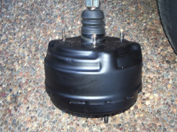
XJ6 Vacuum brake booster from donor car
xj40 Brake booster unbolted from pedal box
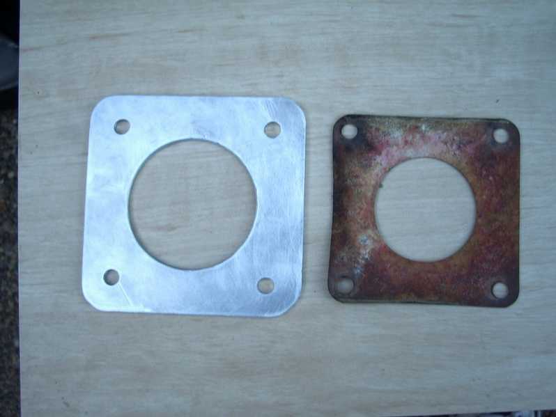
Adaptor plate fabricated using gasket as template
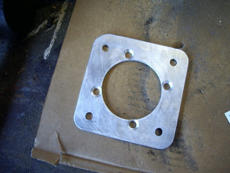
Adpator plate with pedal box holes drilled and countersunk

Pedalbox M8 studs need removing, 2 shown
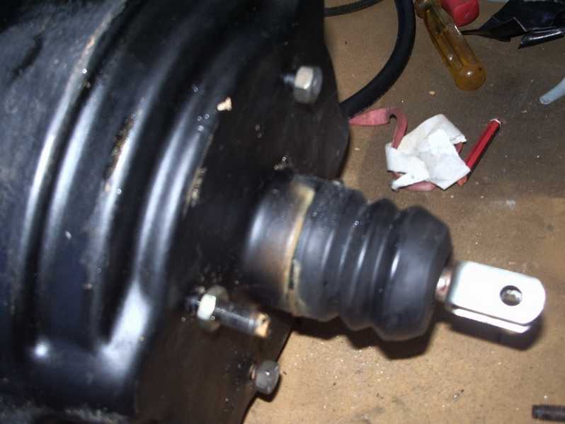
XJ6 booster studs cut down to about 10mm length, 2 shown
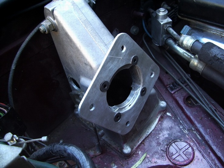
Adaptor plate screwed to pedal box awaiting booster
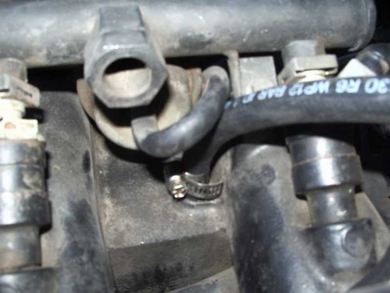
1/4" vac line attached to spare connection on intake manifold
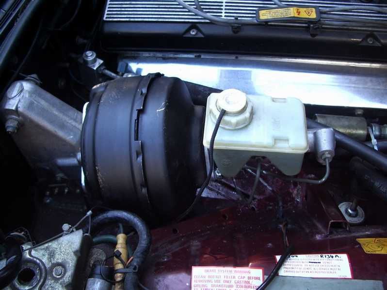
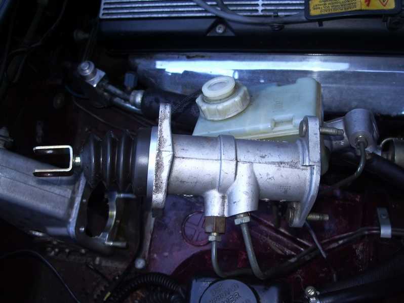
Steering fluid tank moved for access, booster in place
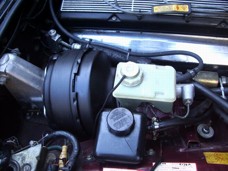
All installed and working, plenty of room for everything!
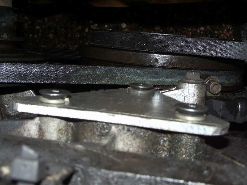
Hydraulic pump removed and cover plate fitted

Hydraulic bits removed, ebay here I come !
|
Jaguar 1987-89 XJ40 Brake booster conversion
This is a modification I made to my own 1989 Sovereign and is the result of hunting around in scrapyards, cutting and drilling 5mm sheet alluminium to fabricate 2 plates and some trial and error. I cannot say whether this modification will work on your XJ40, and I cannot accept any responsibility for anything that doesn't quite work like mine did.
This will only be suitable for 1987-89 XJ40's fitted with the Girling Hydraulic brake booster system, and with no SLS installed. I came up with this modification after noticing how similar the Girling system on an XJ6 was when compared to the XJ40 in terms of the master cylinder and its dimensions.
The Booster I used was from a 1982 Jaguar XJ6, and I believe that most XJ6 and XJS models from the 80's use a booster which is dimensionally similar and may be used without too many problems. Mine cost me AU$85 from a wreckers yard and with a cleanup and a coat of paint works great ! My car is a Right Hand Drive, and the booster fits without any bodywork modifications, there is plenty of room. I am not sure if anything is in the way on a LHD car, but if there is I suggest you move it out of the way.
Total Cost of this project :-
Pre-owned XJ6 booster $85.00
5mm alluminium plate ( offcut from local engineers merchants ) $10.00
7 x M8 Counter sunk socket head bolts 16mm long. $ 7.00
1.5m of ╝" vac/fuel hose $15.00
TOTAL COST $ 107.00
( That's for everything, nothing extra to buy !!! - maybe a bit of paint ? )
Here's how it's done:-
Testing The 'New"Booster before you start doing anything
Ě Test your XJ6 brake booster ! There's no point going ahaead if your XJ6 pre-owned booster is duff. Connect the booster to a vacuum source on the XJ40 intake manifold. Mine had a spare blanked off source just behind the fuel regulator toward the front of the engine, right on top of the manifold. It was a 3/16" tube just sitting there with a black rubber cap on it. If yours doesn't have a vac source available, you may have to make one - I guess you could drill and tap into one of the many points on the manifold that look like they are intended for the purpose. ( Just next to the aircon vac tube might be a good place ! ) Be careful not to get any metal shavings in the manifold though ! )
Ě With the engine off, it should be very hard to push the actuator into the booster. If it moves easily the booster may be no good. However, with the engine running pushing the actuator will be very easy and the piston should move in and out at the rear of the unit.
Ě When you are happy that you have a good working booster, disconnect the vac hose and give it a clean and a coat of paint to make it look fit for your jag !
Removing the old hydraulic booster
Ě With the ignition off, depress your brake pedal until the accumulator pressure has been dissipated and the pedal goes hard
Ě Remove 2 x nuts Holding Master Cylinder to Brake booster and gently slide the master cylinder out of the way being careful not to damage the brake pipework.
Ě Remove 2 screws holding the power steering fluid tank and move it out of the way to allow better access to brake booster area.
Ě Remove 2 x rubber bungs on the pedalbox to allow access to the pedal/booster fixing pin, and after removing the circlip gently knock out the pin.
( You do not need to remove the pedalbox, it's fiddly but you can get to the pin and circlip with a pair of snipe-nose pliers ).
Ě Undo the 4 nuts holding the hydraulic booster to the pedalbox, undo the 2 hydraulic lines from the booster, and remove the whole unit. The Hydraulic lines can be moved aside for removal later.
Preparing the hardware
Ě The pedalbox has 4 x M8 studs sticking out of the front of it. These can be simply unscrewed, you may need to use a strong pair of pliers or grips as they may be a bit stiff - but they do come out !
Ě Cut down the 4 studs on the front of your XJ6 booster to about 10-12mm length, remember to put nuts on first to clear the threads after you have hacksawed them off. ( they are too long when offered up to the pedalbox if not cut down ).
Ě My Booster had a gasket which I used as a template to mark out the adaptor plate which you need to fabricate yourself which fastens the booster to the pedalbox. ( You will see that the studs and holes don't line up at all ! )
Ě The adaptor plate I made was 130mm square and made from 5mm thick alluminium plate. Mark it out before you do anything else. You can make templates by placing a piece of card/paper over the booster studs and on the pedalbox holes. Make sure that the fluid reservoir on the master cylinder will be level when the booster is fitted - check it before you start drilling.
Ě When you are happy with the paper version mark up your plate and drill the holes. I used a 10mm drill for the pedalbox holes, countersunk deep enough for M8 screws, and 8mm holes for the booster studs. The big hole in the middle I cut 75mm, just because I had a cutter that size, but 60mm would be better as my hole was verging on the 'too big' side of things.
Ě Cut off the corners and round them off with a file to make it look nicer, and make sure that there are no burrs anywhere, it needs to be nice and smooth.
Ě The brake master cylinder needs to have the 2 mounting holes opened up as the studs on the XJ6 booster are slightly bigger. I used a 10mm drill.
Putting the vacuum system together
Ě Nearly Finished ! The adaptor plate can now be screwed onto the pedalbox using M8 x 16mm screws ( anything from 8-16mm length will be OK )
Ě The brake booster can then be offered up the the pedalbox adaptor plate, making sure that it's the right way up and that the master cylinder fluid tank will be level and that the Vacuum connection is on the engine side of the booster. You will find that it goes straight in, and the booster actuator should line up with the brake pedal with a bit of adjustment. Once the nuts are on, ( I only fit 3 ! ) insert the pin back through the pedal/booster connection and replace the circlip. ( I cheated here and drilled a small hole through the pin and used a split pin to secure it instead of the circlip.)
Ě Press the brake pedal and check that the pedal is quite hard to press and the the brake light works OK. Because of the 5mm plate, the brake light switch may need to be adjusted simply by slackening off the 3 fixing screws and moving it before tightening the screws again. ( This is mounted on the side of the pedalbox )
Ě Now the Master Cylinder can be offered up to the booster and secured in place with the 2 nuts and washers . It just fits right on there, easy as that !
Ě Connect the booster to the Manifold Vacuum , I used ╝" fuel hose and an adaptor to 5/8" which is what my booster connection used. I also fitted a check valve ( non -return valve ) in line which I also got from the Donor XJ6 as part of the booster. Tighten up all the hose connections and run / secure the hose away from the hot exhaust side of the engine. ( I used cable ties along the fuel rail )
Ě Replace the steering fluid tank and bolt to inner wing in original holes.
Removing the other unwanted parts
Ě Thats the install complete, but what ever you do, don't do what I did - please don't start your engine! HSMO everywhere, lots of mess to clean up, an extra hour of work that you didn't really need because the pump is still on the car!
Ě The old Hydraulic stuff has to come off. Basically it just unbolts from the car without any problems at all. The only fiddly bit is the hydraulic pump. I removed my top radiator hose so that I could get better access. I just about managed to get the 3 bolts out using a small socket wrench without having to remove the cooling fan, but it's very tight and you need patience. I then used the pump as a template to make a cover plate that bolts on where the pump came off. It's just a triangle shaped piece of 5mm alluminium with 3 x 10mm holes drilled in it. I made a paper template using the pump as a guide and drilled to fit. That area of the engine is dry, so there is no need for a gasket, just a plate to keep dust out.
Ě The other bits to come off are, HSMO tank, Valve Manifold, Accumulator assembly and all associated pipework. Disconnect the electrical connectors and make a note of which wires go where for disabling the warnings - later.
Ě Put the top hose back on and top up coolant.
Ě After a cleanup and a quick check around the engine bay for stray tools etc, start her up ! The Brake Booster should work right away. My brake pedal felt a little softer than when the hydraulic system was on there, more progressive as you push the pedal, and the brakes work really well.
Ě The low HSMO warning and Low Brake Pressure warnings will be active, so to fix this simply insert a wire link between the pins of each connector pair that connects to the HSMO level switch and Low pressure switch. The High level pressure switch connections are to be left open circuit. ( no link ) The low pressure switch is the red/yellow wire and the high pressure is black/yellow. Each is paired with a brown/pink wire so make sure you get the right one.
Good Luck Jag-Lovers.
Steve Marsden
June 2005.
1989 XJ40 Sovereign, 3.6 Auto.
|


