|
6.14 - Light ECU troubleshooting ( Bruce Taylor,
December 10, 2001
)
|
The following info relates to a strange intermittent electrical problem on a 1992 Daimler/VDP
When the fault is present, all of the following happen:
- The audio warning screams continuously (even with the ignition key out!).
- The bulb failure indicator is on (sure, but read on...).
- The radio works fine but the antenna won't go up (or down if it is already up).
- The direction indicators don't work (no clicking, no flashing, left or right).
- The internal and puddle lamps don't come on when you open doors.
- The internal overhead lamp doesn't come on with its switch either, but the map reading lamp works normally.
- The hazard lamps don't work.
- The keyboard illumination doesn't work.
- Everything else seems to work fine!
Sometimes after a few hours of audio screaming, the fault clears itself spontaneously and suddenly all of the above things work normally! Then for no apparent reason the screaming restarts and all the above failures are back again together.
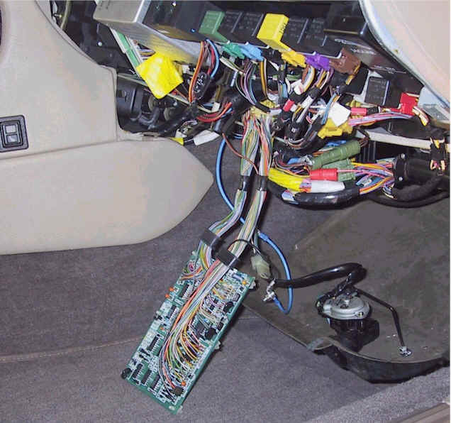
The microprocessor unit (I'll call it the ECU for short, but of course this is not the engine management ECU) is mounted on a vertical bracket at the back of the wiring area behind the passenger side knee bolster. Although the top end is inaccessible it is held by a hook, so it's only necessary to remove the lower 2 self-tapping screws to get the unit out. In addition to torx screws, the ECU cover is secured by 2 rivets with fancy heads to discourage tampering, err, inspection. The screws are quite tight but made of butter, so you may want to push the screwdriver right in to get some bite. Be very careful about this if your screwdriver has a long tip! Some of the hollow screws are just above the internal pc board and the screwdriver could damage traces on the board.
The ECU uses a National Semiconductor COP325 microcontroller. That's an industrial temperature (-40 to +85 deg C) version of the COP425, a 4-bit CMOS microcontroller with 1K ROM that cost about $1 each in the late 1980s. It's a simple, low-density, double-sided pc board with a few ICs and discrete components that would be quite repairable if a schema were available. Unfortunately the makers (AB, of BFM fame) have omitted to stick that on the inside of the top cover!
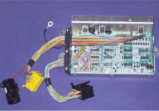
To access the solder side of the pc board, remove the screws securing the 3 TO220 components to the case and snap out the 6 plastic clips. The leads are long enough to test the open pc board in the car quite conveniently with just an extension to the ground lead as shown in this pic : fuel economy is calculated using injector "on" time and distance traveled and is recalculated about every 5 seconds.
Direction indicators are closed, the wires read about 0.1 ohm to ground at the ECU input. When the inputs are open circuit, a DVM reads about 145 mV. This is probably not a DC level and the indicated voltage may depend on the capacitive load. In my case the voltage fell to near zero when the intermittent fault was present. I don't have the proper factory schematics for my car but I found the wire colour coding of the "typical" schematics in Haynes accurate. The New Zealand M.A.P. manual was also helpful because it indicates connector pin numbers, which Haynes does not, although there appear to be some errors such as B159/B13 crossovers.
The construction quality of this ECU was rather mediocre, the 5v regulator in my unit had been soldered squint and the insulating bush just squashed up instead of entering the hole in the case. The board had been wave soldered and some joints did not look too healthy. There were quite a few solder spatters from the subsequent hand soldering of the connecting wires. Because of the solder mask they did not appear to be causing short circuits, though.
I tested the ECU after resoldering each row and it became OK after doing the row in line with the label "KCE DV-0". There is nothing special in this row (like a high thermal mass connection that can give a dry joint if it's not heated long enough). Since I didn't actually see a defective solder joint I can't be sure that was the cause of the intermittent fault. It's possible there was an internal defect in a component which was cleared by the thermal shock of the resoldering and may reappear in the future.
I wouldn't trust this box in a really critical application, but when it fails the main inconveniences are just the lack of turning indicators and the screaming audio warning, which doesn't stop one getting home.
Anyway the ECU then appeared to be running solid so I boxed it up again, using nice 4BA screws (no longer than 0.2", to keep clear of the pc board) in place of all the original fasteners. These are the ideal size (3.6 mm dia) and preserve the British heritage!
There were many different versions for different models, markets and years. My car is VIN 639732. Within the range VIN 594576 to VIN 648923, from 1990 MY onwards, 4 litre models only, the parts fiche shows that USA vehicles were fitted with DBC4968, Canada/Middle-East/Taiwan with DBC4967 and other countries (including mine) with DBC4966. The design changed again from VIN 648924.
A UK Jaguar parts supplier lists the cost of a replacement DBC4966 as GBP 740. Adding shipping and local tax, that is 25% of what we paid in November 2000 for the entire car!
|


